Hi Geatan,
just check wether the miller cap value works for that transistor, you may have to adjust it to get optimum rsults.
just check wether the miller cap value works for that transistor, you may have to adjust it to get optimum rsults.
Hi Geatan,
just check wether the miller cap value works for that transistor, you may have to adjust it to get optimum rsults.
Hello Nico
From past use of the KSC3503, I know that I may need to raise a bit the value of the miller cap and phase lead cap.
The 2SC3423 have a Cob of 1.8 pF , the KSC3503 have a Cob of 2.6 pF
I will check with a 10k hz square wave on a scope.
Btw, I will do my pcb, so it may be usefull to see an image of the pcb routes.
Thank
Bye
Gaetan
Last edited:
delurkin again ...
lookin' good!
i see light at the end of this tunnel and it doesn't look like it will be a train wreck!
🙂
mlloyd1
lookin' good!
i see light at the end of this tunnel and it doesn't look like it will be a train wreck!
🙂
mlloyd1
The references are different..... but you clearly have worked out why it's been done. So in truth, a little thought, seeing the obvious intent of it all, and you've reached an epiphany......
Try this schematic!
Hugh
compensation/stability tweaks?
series RC in parallel with R1?
I've found a input high frequency termination "Zobel" can be useful, adding phase margin, reducing source/vol pot setting dependency
looking at the feedback loop signal path the input Q1 likes a low Z HF AC gnd at its base
also can fliter some RF from the input
I know Hugh has some ideas on feedback and amplifier voicing but I hate to see all of the compensation bypassing the output stage - "TMC" or 2-pole compensation both would allow loop gain to be maintained to a higher frequency around the output stage
earlier output Zobel design was questioned - the main load difficulty is cable capacitance
due to the desire for small flexible cable headphones can have higher cable C - the amp should be stable into a few hundred pF to at least a few nF
while sim will not be definitive due to modeling limitations a look at output behavior with a step current appied to the output or a V step in series with the modeled cable Cload can show some useful features - AC analysis is less useful than .tran based sims
Last edited:
Hi jcx,
What you say is valid, Could this be the reason for the "standard 120 ohm" series resistance in the output of the headphone amplifier. I simulated with and without. Without the series resistance there is most definately instability if the leads are seen as very capacitive.
What you say is valid, Could this be the reason for the "standard 120 ohm" series resistance in the output of the headphone amplifier. I simulated with and without. Without the series resistance there is most definately instability if the leads are seen as very capacitive.
JCX,
The cable C plus speaker L forms a tank circuit, lowering its Q significantly with added series resistance will dampen excitation.
The cable C plus speaker L forms a tank circuit, lowering its Q significantly with added series resistance will dampen excitation.
Hugh, please decouple the input from ground by your usual method 10 OHMS..., you still have an ground loop issue even thought it is called virtual ground, unless you are planning one VG per amp.
Nico
Hugh
I agree with Nico.
You don't need any more Professors !
SandyK
Member
Joined 2009
Paid Member
Guys, it's looking really good. I'm not sure that I was able to 'direct the thread' or whether the thread was able to direct me but so far it's turned out very interesting and in my view a truly team effort 🙂
And with the design phase coming to a close it's perhaps a good moment to let you know that I have some business trips and other things that will reduce my available time for awhile. But if all goes well I expect I'll have some pcb's from Hugh and in my 'inventory' soon enough !
And with the design phase coming to a close it's perhaps a good moment to let you know that I have some business trips and other things that will reduce my available time for awhile. But if all goes well I expect I'll have some pcb's from Hugh and in my 'inventory' soon enough !
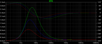
Another nitpick, I scrutinize the value of C3. The graph shows the AC current through R9 (bootstrap source) in mA, for values of 100uF, 220uF, and 470uF (I believe the AC analysis assumes an input voltage of 1V). Normally it is very low, but has risen considerably at 20Hz (lower is better, the bootstrap is supposed to be a CCS). What I don't know is what effect this has on the actual sound.
This should probably wait until someone prototypes it, I just want to point this out. I've been uneasy about the descending value of C3 over time.
- keantoken
This should probably wait until someone prototypes it, I just want to point this out. I've been uneasy about the descending value of C3 over time.
- keantoken
Attachments
JCX,
I'm having some difficulty with 'I hate to see all of the compensation bypassing the output stage'! What do you precisely mean by this?
A Zobel on the input is a good idea, what values do you have in mind? I have amended the zobel cap from 100nF to 22nF; this was a misprint; I'd never intended such a large cap in the first place.
Nevertheless, I think we are reaching the point where this is becoming a simfest; we need to build the damn thing and inspect the performance subjectively and objectively with waveforms.
The intention has always been to build something simple, effective, inexpensive, and relatively high performance. But it is not the ultimate; that would be, I feel, an SE design.
Thanks for your valued input.
Kean,
The value of C3 is not particularly critical. You can get away with about 22uF if you throw away a little bass response. On my AKSA, I've tried as little as 47uF and as much as 470uF and the differences are far less than you'd expect. Certainly very hard to pick subjectively.
I agree about ground lifting, and have another schematic to consider!
Nico,
It is very clear to me that any series R added to the load will dampen any tendency to oscillate, and pull back phase shift. There is probably not much requirement to design for highly reactive loads in this design, given the structure of cans and the fact that the electrostatic ones need veritably power amps to drive them anyway. Thanks for mentioning it, however.

Hugh
I'm having some difficulty with 'I hate to see all of the compensation bypassing the output stage'! What do you precisely mean by this?
A Zobel on the input is a good idea, what values do you have in mind? I have amended the zobel cap from 100nF to 22nF; this was a misprint; I'd never intended such a large cap in the first place.
Nevertheless, I think we are reaching the point where this is becoming a simfest; we need to build the damn thing and inspect the performance subjectively and objectively with waveforms.
The intention has always been to build something simple, effective, inexpensive, and relatively high performance. But it is not the ultimate; that would be, I feel, an SE design.
Thanks for your valued input.
Kean,
The value of C3 is not particularly critical. You can get away with about 22uF if you throw away a little bass response. On my AKSA, I've tried as little as 47uF and as much as 470uF and the differences are far less than you'd expect. Certainly very hard to pick subjectively.
I agree about ground lifting, and have another schematic to consider!
Nico,
It is very clear to me that any series R added to the load will dampen any tendency to oscillate, and pull back phase shift. There is probably not much requirement to design for highly reactive loads in this design, given the structure of cans and the fact that the electrostatic ones need veritably power amps to drive them anyway. Thanks for mentioning it, however.
Hugh
Last edited:
Hi Sandy, do you agree with my comment above your last post - it seems logical
Hi Nico
Seems very logical to me too. However, I bow to your vastly superior technical knowledge.
Much of my experience in this area is from close association with a basically headphone and headphone amplifier related forum.There the types of headphone amplifiers and headphones in use are quite diverse. There were however >110 HA's constructed to my modified version of a Silicon Chip kit project, and many lessons learned, as well as also testing and reviewing (carefully!) a couple of Graham Slee pre production models.
Regards
Alex
Simfest is true... All thanks to me, of course. 🙂
Perhaps JCX means that both the phase-lead and miller caps are on the VAS, not the actual output. This means that any strange HF behavior after this isn't noticed by the LTP and can go uncorrected.
- keantoken
Perhaps JCX means that both the phase-lead and miller caps are on the VAS, not the actual output. This means that any strange HF behavior after this isn't noticed by the LTP and can go uncorrected.
- keantoken
C4 is supposed to be the phase-lead cap, whatever that means. My observation is that it turns gain down to 1 at high frequencies, aiding stability. I personally would give it a value that rolls off response at not far after 20KHz, why not? But most people don't.
EDIT: To clarify, if C4 is not present, usually there is some sort of gain peaking at 100KHz or above, presumably because the capacitance of the LTP transistors affects the feedback network's ratio at HF.
- keantoken
EDIT: To clarify, if C4 is not present, usually there is some sort of gain peaking at 100KHz or above, presumably because the capacitance of the LTP transistors affects the feedback network's ratio at HF.
- keantoken
Last edited:
Hi Kean,
it is not gain peaking, that is oscilation. If you were to drop the gain to 1 then all you will see is this spike sitting there. You will find this phenomena when the phase has passed through -180 deg but the gain is still above zero dB.
it is not gain peaking, that is oscilation. If you were to drop the gain to 1 then all you will see is this spike sitting there. You will find this phenomena when the phase has passed through -180 deg but the gain is still above zero dB.
Hello
Since the lag compensation or Miller cap and the VAS are the most important step for the signal voltage amplification for the drivers, if the value of the cap are too big, that VAS local nfb are cuting lower than the pole frequency and cut down into high frequencies who are important for good listening. And if the cap his too small it cut higher than the pole frequency and the amp oscillate.
So we use a phase-lead cap as an other local nfb, because with this cap you can keep miller cap at much lower value without the amp oscillating and the sound sound becoming tizzy, bright and fatigueing.
Bye
Gaetan
Last edited:
Does anyone know what C4 does? How was it's value determined?
The $64K question, goes to the heart of the design.
Phase lead, recommended by J Linsley Hood, used on many of his amps.
Improves tolerance of capacitive loads, enables lag comp to be reduced which improves SQ. Very useful on a power amp designed for electrostatic speakers.
How arrived at? Sims, then empirically, in listening tests and square wave analysis.
Difficult to arrive at these values using math analysis as they are tiny capacitors, so layout plays a big part. One of my amps used a single sided board, needed 5pF of PL. When I went double sided, there was more stray capacitance, and I needed to amend it to 3pF. Made a big difference to the sonics, too. Sim assumes there are no parasitics. Play with LTSpice, you will see what happens on a loop gain plot.
Hugh
In light of your post, Hugh, I have an interesting idea.
I suggested in a thread somewhere to decrease the feedback network impedance by a factor of 10. So if we had feedback resistors of 22k and 10k we would use 2.2k and 1k. This was at first met with skepticism as it can bring the LTP out of balance, but John and others acknowledged that there was a significant decrease in distortion. The other advantage of this, that I only realize now, is that your phase lead cap can be substantially larger, (theoretically) making stray capacitance less important.
Unfortunately this theory lacks real-world verification.
- keantoken
- Home
- More Vendors...
- AKSA
- Aspen Headphone Amp