On CSX1 PSU schematic i see T2 12 V secondary with 1VA power efficiency
it is required minimum output power ?
Think about LSK buffer on pcb with on & off switch.
Greetings 🙂
it is required minimum output power ?
Think about LSK buffer on pcb with on & off switch.
Greetings 🙂
Last edited:
On CSX1 PSU schematic i see T2 12 V secondary with 1VA power efficiency
it is required minimum output power ?
Think about LSK buffer on pcb with on & off switch.
Greetings 🙂
I am also thinking about LSK, without buffer, driving input transformer in series for lower cap and higher input impedance. This way I can set the gain of the amp at about 15dB to be similar to my other amps.
clarify
LSK means simply using LSK Jfets instead of Toshibas
you probably mean on some LSK based gain stage , but remember that driving repeater coil demands some muscles (even if input impedance is in ten K area) , so gain stage must have them
muscles , I mean ....... cojones , in fact
so , be careful which gain stage you're choosing
nice
though - I urge you to try it buffered
that would be one step back but , at least , 3 forward
also - do not forget importance of exquisite reg. supply , preferably one per channel
though - I urge you to try it buffered
that would be one step back but , at least , 3 forward
also - do not forget importance of exquisite reg. supply , preferably one per channel
Adding a buffer is quick and easy, I can try it both ways.
Do you think the Buffer can be supplied from the LSK regs?
🙂
Do you think the Buffer can be supplied from the LSK regs?
🙂
......
Do you think the Buffer can be supplied from the LSK regs?
🙂
yup
that's the proper way to do it
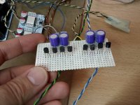
Second test
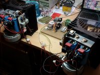
Good days all. Today I have finished the second channel. I connected to speakers and I found that: 1- there is a pop in speaker, 2-amplifier needs 30 minutes of warm-up to adjust the current. I set to 1.43A both and there is a little drift into DC offset, but in +-30mV range. 3- Heatsinks are a little hot, I cannot touch with hand more of a few seconds. 4- Initially, DC offset is high (300mV more or less) but in a few moments descend to +-30mV range.
So, it is necessary a delay to connect the speakers and DC protection, I think.
I used OPUS DAC from TPA and buffer without pot. I do not like sound of Opus DAC. It is very soft for me. But amplifier it is very neutral, I think, very detailed (with orchestal music) and very realistic (piano sound like a piano).
But I need more gain with Opus DAC (2Vrms in accordance with specs) and 86dB speakers.
The next step is connect to my BIII and unbalancer tube stage from Broskie and the buffer with 2sk170 2sj74 of course (output impedance of unbalancer is a few high). And a little of gain before (x4 to x8)...
Attachments

I touch my self and I am bloody cold. Two seconds and brrrrr Que frío!
Congratulations and put muscles to drive it Friend Juan Antonio.
300mv indeed are eleven miliwatts? Not to high power for your 86dB/W Proac.
I would to realize a softstart with dc protection anyway.
Have a good friday and excellent week end for all the group.
Congratulations and put muscles to drive it Friend Juan Antonio.
300mv indeed are eleven miliwatts? Not to high power for your 86dB/W Proac.
I would to realize a softstart with dc protection anyway.
Have a good friday and excellent week end for all the group.
Can I use 240/9240 in the place of vfet if there're no vfet at the future ?, with +/- 4~5V vgs each CH.
Also can I find SCH for BJT input instead of Jfet ?
Also can I find SCH for BJT input instead of Jfet ?
Last edited:
Can I use 240/9240 in the place of vfet if there're no vfet at the future ?, with +/- 4~5V vgs each CH.
........
look in F6 thread
.....
Also can I find SCH for BJT input instead of Jfet ?
plenty of candidates - say Diamond buffers , even OP based buffer stage
Is that transformers are suitable for amplifier? Edcor XS1100 and Edcor XS4400?
I say no.
Try Jensen and in group buys thread you can save money we are +100 today.
List is open for some days....all is welcome.
http://www.diyaudio.com/forums/grou...jensen-transformers-sony-vfet-project-15.html
Best regards
🙂

I have calculated the harmonic distortion with the information obtained of jama:Hello again. I have done some measurements.
0. Equipment used, 1.jpg
1. From 20 Hz to 200KHz (with Zout=50 ohm), 3.jpg and 9.jpg
2. Gain in voltage aprox 3.5, 4.jpg, 7.jpg and 9.jpg
3. To 12 Wrms to 8 Ohm (10Vrms), appear third harmonic
13.jpg, 14.jpg, 15.jpg, 16.jpg and 17.jpg
http://www.diyaudio.com/forums/pass-labs/253411-article-sony-vfets-part-1-a-24.html#post3886828
Total harmonic distortion - Wikipedia, the free encyclopedia
THD@2Khz=3%
Is it correct?
Last edited:
XS1100 , possible candidate if wired with 1 & 1 in series - as primary , and using 2 & 2 as secondaries
XS4400 , possible candidate with two 1's wired in parallel as primary , and two 1's used as secodaries
interesting , myriad of combinations , also for easy balanced input configuration
there are many good xformers around ......
XS4400 , possible candidate with two 1's wired in parallel as primary , and two 1's used as secodaries
interesting , myriad of combinations , also for easy balanced input configuration
there are many good xformers around ......
XS 1100 and XS 4400 bandwith is 10 Hz to 50 kHz only.
Distortion at 1kHz is <0,01% steel core transformer
Jensen wide bandwith is 0.27 Hz to 370 kHz.
Distortion at 1kHz is <0,001% 50 % nickel alloy core transformer.
Result is more open sound with Jensen less distortion
Its your game 🙄
Best regards
Distortion at 1kHz is <0,01% steel core transformer
Jensen wide bandwith is 0.27 Hz to 370 kHz.
Distortion at 1kHz is <0,001% 50 % nickel alloy core transformer.
Result is more open sound with Jensen less distortion
Its your game 🙄
Best regards
Attachments

Last edited:
- Status
- Not open for further replies.
- Home
- Amplifiers
- Pass Labs
- Article - Sony VFETs part 1