I was hoping these would be right for the job.
Invalid Request
There ARE .90 cents each after all, a bit rich for my blood.😱
I couldn't get the link, but I'd suggest an Elna RFS cap.
Think of the price of the transformer. You don't want to degrade its
performance with a lousy cap.
An externally hosted image should be here but it was not working when we last tested it.
too cheap , mine are pure gold..😀

too cheap , mine are pure gold..😀
Same here, hanging in, bypassed with a 100nF 'MKP1837' for extra smooth highs 😀 (1837 is not in this picture)
Attachments

Last edited:
I couldn't get the link, but I'd suggest an Elna RFS cap.
Think of the price of the transformer. You don't want to degrade its
performance with a lousy cap.
Its a digikey link for Panasonic FC...
Link works for me😱
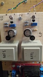
Ref 1 of my CSX 1 does not work properly
I tried to preset the biasing voltages of my CSX 1. The VFETs have not been connected so far. Strange thing. It is impossible to adjust them to lower than some 11V with R7 = 7.5k in the divider of Ref 1 and P1 set to 0 Ohms @ 15V input voltage. Reducing the input voltage to about 12V enables a proper setting @ P1 = 0 Ohms.
Decreasing R7 to 4.3k (P1 = 0 Ohms) allows setting the output voltage to min. 8.5V @ 15V and 7.7V @ 13,6V input voltage. Both channels show identical measurands.
Ref 2 work perfectly on both channels: R8 = 7.5k, Vin = 15V, Vout = 7.6V @ P2 ~ 3k
There is no layout error on the PCB. Any advice? 😕
my not logical oriented brain says the in REF1 the position of R7 and P1 must be inverse.
but I told this already here
http://www.diyaudio.com/forums/pass-labs/253411-article-sony-vfets-part-1-a-30.html#post3902939
and Nelson said all is o.k.
how did you manage this point WalterW?
🙂
but I told this already here
http://www.diyaudio.com/forums/pass-labs/253411-article-sony-vfets-part-1-a-30.html#post3902939
and Nelson said all is o.k.
how did you manage this point WalterW?
🙂
I did article schematic exactly and all works ok. I never had been any problem with transistors polarization. My csx1 sound wonderful today. Problem in other place.
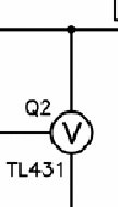
The polarity of the TL431 is correct and I can't find an explanation for the malfunction...
or we have a problem with the orientation of the TL on the board...
Last edited:
Yes, I know that scheme is OK and layout too.
But why don't the TLs regulate properly? P1 is set to 0V and Vout only can be varied to lower values by decreasing Vin. Decreasing R7 also does not really help. Very strange...
But why don't the TLs regulate properly? P1 is set to 0V and Vout only can be varied to lower values by decreasing Vin. Decreasing R7 also does not really help. Very strange...
just adjust it , check and forget
sch is OK , floating regs , blahblah
Yes, I know that scheme is OK and layout too.
But why don't the TLs regulate properly? P1 is set to 0V and Vout only can be varied to lower values by decreasing Vin. Decreasing R7 also does not really help. Very strange...
Yes I have found similar with all of my TL431 regs. I couldn't source 7.5K so put 8.75K in place and I find that I can only get to a minimum of ~6.5V from a (high) input voltage of ~26VDC.
To get to 6.5V output requires ~20V across the 3.3K resistor which is only ~6mA current sunk by the TL431.
That is well within spec of 1mA - 100mA sink capability for these parts.
6.5V may be OK for me to bias up the output VFETs but - like permaneder - I'd love to know why I cannot get down near to Vref at 2.5V?
Could check without the VFets
Juan Antonio, also, you can mount all the components in the board with out the Vfets, and checking and measuring everything, then connect the rest of parts.
Regards from Menorca
There are two differents ref voltages. Try mount on board and check how works. When all ok compare with pcb.
Juan Antonio, also, you can mount all the components in the board with out the Vfets, and checking and measuring everything, then connect the rest of parts.
Regards from Menorca
Drugs helped to solve the problem. After a bottle of Château Villars 2007 I resoldered the 7.5k resistors and started the regs @ 15V input voltage once again. Setting P1 to 0 Ohms showed more than 10.5 V at the output as before. Increasing the pots' value made the Vout rise up to about 11V. From that point on Vout began to decrease again. Now both Ref 1 can easily be set and they are working stable from 15V input. Don't know why. Still very strange... 😉
Yes, I know that scheme is OK and layout too.
But why don't the TLs regulate properly? P1 is set to 0V and Vout only can be varied to lower values by decreasing Vin. Decreasing R7 also does not really help. Very strange...
my not logical oriented brain says the in REF1 the position of R7 and P1 must be inverse.
but I told this already here
http://www.diyaudio.com/forums/pass-labs/253411-article-sony-vfets-part-1-a-30.html#post3902939
and Nelson said all is o.k.
how did you manage this point WalterW?
🙂
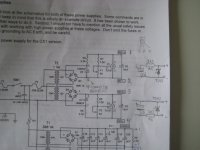
I've been struggling with the 3k3 also, see picture of my notes during the build. But if you simplify, like my drawing, it all makes sense

What I recall is that I could adjust from about 4 a 5 volts up, both ref 1 and 2.
But my little 12V 6VA transformers output 16 - 17V AC, so input voltage is around 23V for the TL431
Attachments
Walter congrats. You sure build them fast.
How would you compare the sound of this amp to the F5v3 you completed last year?
Took me some days to answer this😀 And I don't have golden ears....
The CSX1 sounds warm, fluid en very musical, but every time I switch from VFET to F5Tv3, I am surprised that the F5T has it all too.
The F5T maybe sounds a bit flatter, but more precise. They do sound different, I can hear that🙂
BTW: The P3 trimpot for playing with harmonics in the F5T is still untouched, in the middle position.
Curious for reviews of others, who can better describe what they hear...
Walter
- Status
- Not open for further replies.
- Home
- Amplifiers
- Pass Labs
- Article - Sony VFETs part 1