Ah, so you decided to drop the LM317/337's and follow the Pass schematics for the PSUs?
Yes, and lengthen the L brackets so that they spread right across the heatsink to get better thermal tracking between the 2 VFETs.
Maybe investigate the noisy R-core further? Something is not right when they make a sound, the ones I used were very quiet....
After a few days off I have finally found where the problem lies. One of my rectifier boards is drawing a lot of current. This is causing the buzzing in the R-Core, when I pull that output tap from the R-Core and connect it to another rectifier board it is totally silent!
I had been testing the IRFP240/9240 regulators with big resistors as loads and getting the buzzing - then on one of my switch off cycles with the problem rectifier board I must have got a huge discharge of some kind because my TV lost HDMI connection for a split second.
I can only assume that some kind of EMF got picked up by the HDMI cable causing it to lose sync between the receiver and TV momentarily.
I figure that could quite easily blow VFETs with no problem whatsoever. I will replace and test thoroughly before I proceed further!
After a few days off I have finally found where the problem lies. One of my rectifier boards is drawing a lot of current.
Defective rectifiers? Or defective capacitors behind it?
Good you almost solved it!
Defective rectifiers? Or defective capacitors behind it?
Good you almost solved it!
Defective rectifier or rectifiers, not sure but probably just 1 of the 4 that make up the bridge.
Unloaded the rectifier board shows no issue, but when loaded there is something wrong - buzzing of the transformer and some kind of spike on turn off.
I have ordered another board and 4 more diodes for the bridge, figure that is the safest way.
Alas I have solved my problem, but now I have a load of rebuilding to do. Some of the comments made me think quite hard about the length of the L bracket; so I ordered a new one that will go right across the length of the heatsink so that both VFETs should track at similar temperatures.
I have rebuilt the bias boards as well, but will probably keep the original LM317/337 based power regulators as it transpires that they are perfectly OK.
ianc13
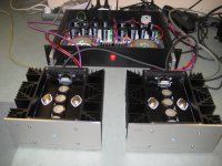

Not much going on here....so post some pictures for inspiration😀
My front panels arrived.
Seriously good looking monoblocks!
Now that you have been living with them for a little while how do you find them?
My build is progressing, albeit very slowly at the moment. Hopefully get to the listening/testing stage early next week.
I keep on listening to them...such a juicy, fluid, bright sound, my F5T sounds a bit dull compared to these 🙂
Hi,
heatsinks from a 4U chassis are enough for a stereo block or must I do 2 monoblocks ? or maybe 5U (but it's big...) ?
(does smaller than 19" chassis with heatsinks exist for monoblock ?)
heatsinks from a 4U chassis are enough for a stereo block or must I do 2 monoblocks ? or maybe 5U (but it's big...) ?
(does smaller than 19" chassis with heatsinks exist for monoblock ?)

Not much going on here....so post some pictures for inspiration😀
My front panels arrived.

Walter congrats. You sure build them fast.
How would you compare the sound of this amp to the F5v3 you completed last year?
How would you compare the sound of this amp to the F5v3 you completed last year?
Today I finished the second channel of the CSX1 and have been listening to it for two hours.
It sounds.... different....very, very detailed in the mids, big soundstage. Very good control and details of frequencies under 80Hz, amazing! It surprised me, a test tone with 34 Hz made my whole room shake....
I think this one is even more detailed than my Aleph J 😱 But I have to do 1 on 1 comparison.
Highs are not so pronounced, but they are there.
There is a lot of coloration, especially in the mids and with the BA3 as a preamp in front of it. Is that the third harmonic content I'm listening to?
The amp really has a sound of his own and is easy to listen to.
Gain is higher then I earlier reported. I removed the 220 Ohm output resistors of the DCB1 😛
The bias voltages from the second channel are 6.4 and 9.4Volt, totally different from the other channel. So the VFETs I have, vary a lot.
When more people are building this amp soon, I'm curious what others will report.
I listened to it with the DCB1 in front and sometimes with the 'BA-3 as a pre' in front. Speakers are big 4 Ohm three ways.
Walter
I thought big caps after regulator could led to instability of the reg?
A large output capacitor will over-damp the regulator, slowing it down, but it will still be stable. A small output capacitor will preserve its speed, and it can still be stable. However, an intermediate range of values of output capacitor can cause instability. This is caused by two of the circuit poles being too close together. With a larger or smaller cap though, they are too far apart to cause a problem.
A large output capacitor will over-damp the regulator, slowing it down, but it will still be stable. A small output capacitor will preserve its speed, and it can still be stable. However, an intermediate range of values of output capacitor can cause instability. This is caused by two of the circuit poles being too close together. With a larger or smaller cap though, they are too far apart to cause a problem.
is it the same case for the 20000uf cap after the mosfet regulator on the permaneders CX1 PCB ?
Last edited:
is it the same case for the 20000uf cap after the mosfet regulator on the permaneders CX1 PCB ?
Yes, this regulator would be slowed down by that very large output capacitor.
You can try it with the original Pass value capacitor first. You do need a large enough cap at the output to ensure stability, so don't make it any smaller than that. Remember that this is a still a feedback regulator.
10uf original , 20000uf in the PCB model, large range to try 🙂
what about the 220uf in the signal path ? is it worth to use a good one or bypass it?
what about the 220uf in the signal path ? is it worth to use a good one or bypass it?
10uf original , 20000uf in the PCB model, large range to try 🙂
what about the 220uf in the signal path ? is it worth to use a good one or bypass it?
Those are certainly critical parts, because they couple the secondary windings to the VFET sources, although not much current flows through them. Use the best parts here that you can.
Those are certainly critical parts, because they couple the secondary windings to the VFET sources, although not much current flows through them. Use the best parts here that you can.
I was hoping these would be right for the job.
Invalid Request
There ARE .90 cents each after all, a bit rich for my blood.😱
- Status
- Not open for further replies.
- Home
- Amplifiers
- Pass Labs
- Article - Sony VFETs part 1