JE and JF parts
I would like to know if these JE and JF parts would work, and whether they will pair well with the KE and KF parts. 2 of the SJ28s are JE where the SK82s are JF, so I'm thinking of getting 2 pairs from CircuitDIY to match the JE/JF parts with KE/KF parts.
I will not build this amplifier anytime soon, as it's probably too complex for beginners like me (still working through Cordell's "Designing Audio Power Amplifier" book), but I'm stocking the parts first before they become unobtainium, so that I will have the parts to work with when I'm ready, probably in a few years time.
Attachments
I am a beginner too. If you reproduce exactly the recommendations of the article, the same power supply, the same heat sink, If you follow the instructions on the starting the engine, tuning the bias, from low to high with care. Did you measure the Vfet with the multimeter? The first is: Between D and S must measure one ohm or less, inverting or not the same resistance, and with a diode probe, between G and D for one side, and between G and S must show the same measure like stupid and common diode. With this you can see if you have a Vfet in your hands.
Go a head mister.
Go a head mister.
...Between D and S must measure one ohm or less, ...with a diode probe...
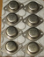
Thanks, the test instructions are very helpful as I was trying to find ways to determine if they're authentic VFETs (got them from China, the source has so far been reliable but it's always better to check).
- Rds are measured to be between 0.5R to 1.0R, I got slight variations when measured from opposite directions, though I incline to think that's due to contact resistance (these transistors are quite old and have a thin layer of rust on their pins)
- For diode probe tests, Vf measured to between 0.43V to 0.49V, and like you described, values are the same from G to D or G to S.
I think is the same that I have, but I will ask.
There are curves I suppose on the webpage Amplimo from Holland.
Best Regards.
There are curves I suppose on the webpage Amplimo from Holland.
Best Regards.
You can use or pair them....Mr Pass Design does not need matched devices unless you parallel pairs.I would like to know if these JE and JF parts would work, and whether they will pair well with the KE and KF parts. 2 of the SJ28s are JE where the SK82s are JF, so I'm thinking of getting 2 pairs from CircuitDIY to match the JE/JF parts with KE/KF parts.
I HAVE MEASURED K60 VFET WITH jG 54 AND jf 24 AND THEY ARE PRETTY CLOSE Vgs...AS LONG AS THE LAST DIGIT OR RANK IS THE SAME..
I have been listening a few days now and I can say, it's worth the effort!
What a nice amp!
The sound is bright, warm, open and detailed. It also gives a big punch in the lower frequencies. I have a nice 10.000 uF Nichicon Gold Tune over the regulated 23V power supply, maybe that helps to give that nice bass. On the Permaneder PCB's there is room for such a capacitor also.
I hope to hear more people talking about this amp..... I'm curious how they like it.
SoundHappy where are you?
IANC13 how are you doing with your build? Found the problem?
Does anybody know how hot the top of the TO3 can be, at max?
In the spec sheet it says Tj / Tch = 120C for the Sony VFETs instead of the "normal" 150C.
In the spec sheet it says Tj / Tch = 120C for the Sony VFETs instead of the "normal" 150C.
i know it will not be sexy but can't we use a piece of aluminium joint with the heatsink ( isolated by thermal pad) on the top of the 2SK82 to make a better heat transfer ?
if normal interface is substantial enough , not worth the fuss
if normal interface isn't substantial enough , make it properly
if normal interface isn't substantial enough , make it properly
IANC13 how are you doing with your build? Found the problem?
After the trauma of destroying obsolete VFETs on a regular basis I took a few days off!
Going to try to figure out if there is a problem in one of the PSU blocks (bad cap, bad wiring etc) tonight and then go from there.
Certainly don't want to kill another P channel part so need to rig up a dummy load that'll draw a few hundred milli Amps and go from there.
i know it will not be sexy but can't we use a piece of aluminium joint with the heatsink ( isolated by thermal pad) on the top of the 2SK82 to make a better heat transfer ?
Why hide these beauties?
As the mighty ZM said, make it proper. And make them visible says I 🙂
After the trauma of destroying obsolete VFETs
Don't worry, they are obsoletes, now get new. 😱
Bonne soire Juanitox.
Don't Panic with the heat in the top of the transistor, the junction is glued in the plate that is used for stay intimately with the heat sink, I make a new draw that attached in this post.
Don't Panic with the heat in the top of the transistor, the junction is glued in the plate that is used for stay intimately with the heat sink, I make a new draw that attached in this post.
Bonne soire Juanitox.
Don't Panic with the heat in the top of the transistor, the junction is glued in the plate that is used for stay intimately with the heat sink, I make a new draw that attached in this post.View attachment 423050
Don't Panic with the heat in the top of the transistor, the junction is glued in the plate that is used for stay intimately with the heat sink, I make a new draw that attached in this post.View attachment 423050
thanks , i will see the heat with my chassis , the summer arrived this week here with 38° celsius outdoor now , bad times for CLASS A 😀
thanks , i will see the heat with my chassis , the summer arrived this week here with 38° celsius outdoor now , bad times for CLASS A 😀
Naw, just get a bigger air conditioner!!!!
😀
How bad would it be to attach the VFETs upside down on the L angle?
They would be horizontally mounted beneath the horizontal part of the L angle with their pins sticking up through to the top side - this would make wiring much simpler!
Am I just asking for trouble here with dissipation issues?
Thanks, ianc13
They would be horizontally mounted beneath the horizontal part of the L angle with their pins sticking up through to the top side - this would make wiring much simpler!
Am I just asking for trouble here with dissipation issues?
Thanks, ianc13
there is no problem with that, besides it is less attractive....
Less attractive maybe, but it will allow me to reposition the buffer, bias, xformer and power stage wiring all on top of the L bracket.
Only the power regulators would be less accessible, but going with Nelson's IRFP240/9240 design they do not require adjustment anyway.
This should help construction, diagnosis and hopefully mean that I do not keep killing VFETs

- Status
- Not open for further replies.
- Home
- Amplifiers
- Pass Labs
- Article - Sony VFETs part 1