Thanks everybody!
@ZM: now I know what you mean.
@woody, that's an excellent idea, if adding one additional SK88 doesn't work I try that.
@Mr. Pass and Chris: thanks for the calculations, I understand.
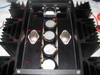
This 100+ watt heat a channel is a lot to deal with. Theoretically 4 x SK88 should do the trick: 0.9K/W /4 = 0.225K/W. But I always forget that's probably at 70-80C when they dissipate better than at 50C.
So other builders beware, calculate 30% extra for your sinks.
Also the L profile gives an extra thermal junction. See pic.
If I get my VFETs down to 60C on top, I settle for that.
@ZM: now I know what you mean.
@woody, that's an excellent idea, if adding one additional SK88 doesn't work I try that.
@Mr. Pass and Chris: thanks for the calculations, I understand.
This 100+ watt heat a channel is a lot to deal with. Theoretically 4 x SK88 should do the trick: 0.9K/W /4 = 0.225K/W. But I always forget that's probably at 70-80C when they dissipate better than at 50C.
So other builders beware, calculate 30% extra for your sinks.
Also the L profile gives an extra thermal junction. See pic.
If I get my VFETs down to 60C on top, I settle for that.
Attachments
Thanks everybody!
@ZM: now I know what you mean.
@woody, that's an excellent idea, if adding one additional SK88 doesn't work I try that.
@Mr. Pass and Chris: thanks for the calculations, I understand.
This 100+ watt heat a channel is a lot to deal with. Theoretically 4 x SK88 should do the trick: 0.9K/W /4 = 0.225K/W. But I always forget that's probably at 70-80C when they dissipate better than at 50C.
So other builders beware, calculate 30% extra for your sinks.
Also the L profile gives an extra thermal junction. See pic.
If I get my VFETs down to 60C on top, I settle for that.
I have a number of SK88-150's. I was thinking of a minimum of 3 if not 4 per side for the pair (2SJ28/2SK82).
Regards,
Dan 🙂
one mono block done !! next week the power supply build , stay tuned😀
An externally hosted image should be here but it was not working when we last tested it.
Dear Friend The aspect of your construction is amazing but I think you need a fan for this heatsinks.
who say it"s an amp? like that it's just for a barbecue 😀
i will try with small bias to see how it goes 🙂
i will try with small bias to see how it goes 🙂
Power supply for a buffer.
This puzzles me because all grounds in my F5 went back to a common star ground on the chassis. So how could my +/-12VDC supply be not referenced back to the same star (chassis) ground as the +/-24VDC supply for the amplifier?
Regards,
Dan 🙂
However if it shares ground with the
main supply of the amplifier you will not have the input isolation of the transformer.
This puzzles me because all grounds in my F5 went back to a common star ground on the chassis. So how could my +/-12VDC supply be not referenced back to the same star (chassis) ground as the +/-24VDC supply for the amplifier?
Regards,
Dan 🙂
More about grounding. All my previous projects had anything with a ground sign go back to a star chassis ground through a CL-60. For this V-Fet project I'd like to do a remote power supply case that feeds the +/-24 through a Neutrik Powercon (one for each channel) connector powerCON 20 A - Neutrik. So would the negative speaker post and the ground of the RCA input connect to the ground of the remote power supply chassis or to a chassis ground on the amplifier enclosure? Since I'll have two separate enclosures here, one for the power supply and one for the amp. I'd like to iron out this issue before I start ordering parts.
Regards,
Dan 🙂
Regards,
Dan 🙂
Last edited:
both (and every metal !) chassis safety grounded
central audio gnd point connected via NTC to local chassis
central audio gnd point connected via NTC to local chassis
Last edited:
So an NTC in each enclosure with the star ground of the outboard enclosure tied back to the to the star ground of the power enclosure?
Regards,
Dan 🙂
Regards,
Dan 🙂
So an NTC in each enclosure with the star ground of the outboard enclosure tied back to the to the star ground of the power enclosure?
Regards,
Dan 🙂
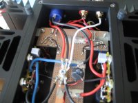
Look how I did it, Central ground point, between the elco's coming from the neutrik. With NTC 10 Ohm to case. Also speakerconnector - to central ground point. Input winding of transformer not connected to ground (not on picture)
Attachments

Look how I did it, Central ground point, between the elco's coming from the neutrik. With NTC 10 Ohm to case. Also speakerconnector - to central ground point. Input winding of transformer not connected to ground (not on picture)
So the only NTC you have is in the amplifier enclosure? The power supply enclosure would still have to be grounded bur without an NTC?
Regards,
Dan
- Status
- Not open for further replies.
- Home
- Amplifiers
- Pass Labs
- Article - Sony VFETs part 1