Today I powered up my first monoblock VFET amp. All went well. No magic smoke 😎
I am listening to it now, Left channel the VFET, right channel the ACA amp.
The VFET has very little gain, so start building gain stages...😛
I guess around 6 dB gain or less. I had to adjust the gain for my right channel with the ACA, around -11 dB to let them play at the same level.
With RCA shorted dead silent.
With interconnect to my DCB1 I hear a little high hum, but no big deal. Maybe the Zout of the DCB1 isn't low enough.
I will post some pictures tonight.
Walter
Hello WalterW, Congratulations!! JBOZ works very well for my system. I never have hear my PROAC so good...
and how does it compare to ACA? 🙂Today I powered up my first monoblock VFET amp. All went well. No magic smoke 😎
I am listening to it now, Left channel the VFET, right channel the ACA amp.
The VFET has very little gain, so start building gain stages...😛
I guess around 6 dB gain or less. I had to adjust the gain for my right channel with the ACA, around -11 dB to let them play at the same level.
With RCA shorted dead silent.
With interconnect to my DCB1 I hear a little high hum, but no big deal. Maybe the Zout of the DCB1 isn't low enough.
I will post some pictures tonight.
Walter
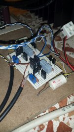
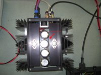
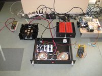
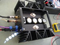
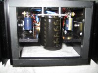
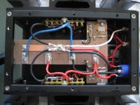
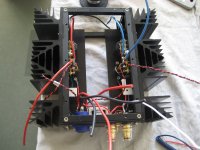
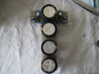
Here are some pics... It is really lots of work building point to point, but I enjoyed it very much.
It's a bit tube style, in the past I build a lot of RF transmitters, also PtP...Good old QQE 06/40's 😀
Now have to build the second channel so I can do some serious listening, pfff...
I hear already good things in the mid sections, voices sound very good, so it is promising....
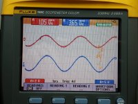
Amp behaves very well, temperature just near the VFET is around 59C, bit high, heatsinks max. 52C. I can't measure at the VFET because my probe wont measure shiny metals🙁
The whole amp draws about 120 Watt at 230V.
My Vreg is 23 Volt, and bias is 1.52 A. Offset stays within a few tenths of mV.
I started adjusting with Vrefs both at 12.0 V (as in the article) and then the amp already pulls 600 mA. I was expecting to start from zero mA 😱
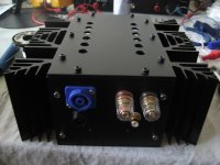
I now have to design a nice frontplate and think of leaving the top off, it's just so beautiful...
It's a bit tube style, in the past I build a lot of RF transmitters, also PtP...Good old QQE 06/40's 😀
Now have to build the second channel so I can do some serious listening, pfff...
I hear already good things in the mid sections, voices sound very good, so it is promising....
Amp behaves very well, temperature just near the VFET is around 59C, bit high, heatsinks max. 52C. I can't measure at the VFET because my probe wont measure shiny metals🙁
The whole amp draws about 120 Watt at 230V.
My Vreg is 23 Volt, and bias is 1.52 A. Offset stays within a few tenths of mV.
I started adjusting with Vrefs both at 12.0 V (as in the article) and then the amp already pulls 600 mA. I was expecting to start from zero mA 😱
I now have to design a nice frontplate and think of leaving the top off, it's just so beautiful...
Attachments
-
 adjust-top.jpg316.4 KB · Views: 428
 -
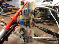
 adjusting.jpg351.7 KB · Views: 419
 -
 bottomplate.jpg269.8 KB · Views: 386
 -
 playing.jpg328.4 KB · Views: 416
 -
 topside1.jpg359.8 KB · Views: 417
 -
 frontside.jpg285.2 KB · Views: 411
 -
 bottom-in.jpg328.3 KB · Views: 610
 -
 prepared.jpg356.3 KB · Views: 607
 -
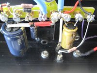 ptp.jpg459.4 KB · Views: 632
 -
 TL431.jpg387.9 KB · Views: 659

Thanks ZM!
The Fugly is the highest, one can get in the Pass section 😀
The Sony VFET's are tube like solid state transistors, so building them this way is the right way....
Walter
The Fugly is the highest, one can get in the Pass section 😀
The Sony VFET's are tube like solid state transistors, so building them this way is the right way....
Walter
though , one Papa's "nice" or "shiney" is worth more then myriad Fugly!s

(Toob Fugly! is ......... uber Fugly!)
(Toob Fugly! is ......... uber Fugly!)

Congratulations again, your materialization is a lot more beautiful mine. Try JBOZ as gain stage.
The VFET has very little gain, so start building gain stages... I guess around 6 dB gain or less.
Odd, I get a consistent 11 or 12 dB. Did you do anything different?
😎
Thanks Jama, I have a BA3 as a preamp that I will use...Congratulations again, your materialization is a lot more beautiful mine. Try JBOZ as gain stage.
Odd, I get a consistent 11 or 12 dB. Did you do anything different?
😎
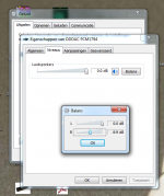
I don't know if the Windows 7 volume balance is a good indicator of dB...see pic.
Attachments
Gain is low, I followed exactly the CSX1 schematic. Only thing different is the 10.000uf capacitors after the regulators. I do not use the JFET buffer.
With the 'BA3 as a preamp' I can get it to high volumes, everything sounds nice though..
With the 'BA3 as a preamp' I can get it to high volumes, everything sounds nice though..
Strange I measured my REF1 voltage at the 2SJ28 it is 11.4V
And REF2 at the 2SK82 is 8.1V......
And REF2 at the 2SK82 is 8.1V......
- Status
- Not open for further replies.
- Home
- Amplifiers
- Pass Labs
- Article - Sony VFETs part 1