I wasn't reffering to the tracking...just about a previous post.
The tracking is good when one rail fails so that you won't get dc current at the output of an op-amp or worse when left with one rail only.I'm thinking that maybe it might be useful also if the supplied stage gets into clipping to have symmetrical clipping.
The tracking is good when one rail fails so that you won't get dc current at the output of an op-amp or worse when left with one rail only.I'm thinking that maybe it might be useful also if the supplied stage gets into clipping to have symmetrical clipping.
**
I think the solution you show at post 143 written in red works.
What is the question ?
May be, you do not need zeners at the regulators Adj pin, because there is a denoiser. Could be LM317 337 are good enough thanks to the D noiser.
In other words I think zener + D noiser is overkill that does not add low noise wise.
The only way to make sure is building these two solutions and measure.
In the LM317 337 solution you can tweak the output voltage with right resistors. I had the trouble of a +16V 15.6V psu, I could tweak equal with a // resistor.
Zeners do not come with accurate same voltages.
I understand you want to modify a + - 8V regulated PSU to + - 20 V by changing 8V regulators to 5V regulators and adding zener diodes.@mchambin
it was this post what i was talking about:
https://www.diyaudio.com/forums/power-supplies/359652-fine-ic-voltage-regulators-15.html#post6335611
I think the solution you show at post 143 written in red works.
What is the question ?
May be, you do not need zeners at the regulators Adj pin, because there is a denoiser. Could be LM317 337 are good enough thanks to the D noiser.
In other words I think zener + D noiser is overkill that does not add low noise wise.
The only way to make sure is building these two solutions and measure.
In the LM317 337 solution you can tweak the output voltage with right resistors. I had the trouble of a +16V 15.6V psu, I could tweak equal with a // resistor.
Zeners do not come with accurate same voltages.
Last edited:
yes...i already started doing it, but i used a lm340(+15v ) plus 5v1 zenner and motorola 7906ct plus 3x 4v7 diodes as i couldn't find a suitable 7905 or 7915 at hand...the 100ohm denoiser feedback resistor will be 330 ohms for the lm340 positive rail and 100ohms for the negative rail as the negative rail in op-amps has always better psrr due to the long tail ccs.
Last edited:
I would not touch beforehand, the 1K 100R that feedback noise to the regulator. I guess those resistor values were tweaked for an optimum de noising.
With the mods you do changing regulators, who knows; You might feedback too little giving less de noising or too much giving oscillations.
The issue of a rail that should be quiter than the other because of not the same PSSR at the preamp circuits, should be solved there with appropriate decoupling.
Solving this at the PSU is what I call a pathological interaction.
Well, may be, it's ok in a DIY world for a one shot PSU / Preamp.
i'll just try my best...i just assumed that 20vdc/8vdc ratio should be reflected in the denoiser resistors ratio too...so maybe 270 ohms would be better than 100 ohms but you might be right and see everything going crazy after such change.At the same time the decoupling/filtering capacitors are more effective at a higher voltage.
Could you possibly help me with commenting my idea if there's anything wrong with it? I already built one regulator like this for +-10v supply rails for a headphones amp.
That should work as long as you manage to keep the extra feedback loop stable. When you change the 100 ohm to some higher value, you increase the loop bandwidth which might lead to instability.
A simple and effective test to see stability and load regulation.
With a load resistor you switch on and off, you'll see ( with an oscilloscope ) wether it rings and the step amplitude.
With a load resistor you switch on and off, you'll see ( with an oscilloscope ) wether it rings and the step amplitude.
"Chop Chop Box" is the name of a power supply transient test load project, (actually several projects), here on diyAudio. Complete designs, including Gerbers, are presented.
I had a look at the chop chop box.
Well, give me a relay and a capacitor, I make you one. The basic ringer circuit.
There no need for accurate timing.
The ability to switch high current is needed.
A relay contact is perfect for this.
No Gerber, no PCB, no oscillator, no MOSFET, no electronics.
Well, give me a relay and a capacitor, I make you one. The basic ringer circuit.
There no need for accurate timing.
The ability to switch high current is needed.
A relay contact is perfect for this.
No Gerber, no PCB, no oscillator, no MOSFET, no electronics.
Relay contact bouncing can be troublesome.
It might bounce when closing.
There is no bouncing when opening, this gives a clean step, good to see the PSU under test ringing and the step amplitude.
I was doing this test, without any switching equipment, just holding the load resistor by hand with the scope on a slow horizontal sweep.
It might bounce when closing.
There is no bouncing when opening, this gives a clean step, good to see the PSU under test ringing and the step amplitude.
I was doing this test, without any switching equipment, just holding the load resistor by hand with the scope on a slow horizontal sweep.
...tracking is good when one rail fails so that you won't get dc current at the output of an op-amp or worse when left with one rail only.....
Tracking is *usually* one-way. Negative tracks the positive, or the other way. In the example attached, if the + fails, the - will fall very low; but if the - fails (for example a blown power transistor) the + is not affected (does not even 'know' the - has failed).
Yes, there are cross-cross-tracking systems so any failure kills all. (Usually for more complex many-rail systems.)
Your point about asymmetrical clipping is valid, but how different do you expect your two rails to be? 1%, who cares? 10% is hardly audible. 25% is "a sound", and a fuzz-guitarist would care..... but regulators normally hold 5% of nominal or else dead. Anyway clipping is (except in fuzz music) "bad", and avoidable.
Attachments
The + rail is most likely to fail usually.Maybe there are other reasons for tracking too,like the - rail left ripple caused by the load itself to be in phase with the + left ripple ...
I would not worry about a rail failure for a preamp.
A rail failure is to fear for power amplifiers that have dual rails and DC coupling to the speaker.
It is likely to destroy the speaker.
Out of that case, I do not see more trouble.
A rail failure is to fear for power amplifiers that have dual rails and DC coupling to the speaker.
It is likely to destroy the speaker.
Out of that case, I do not see more trouble.
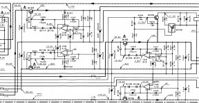
I just saw something different in the kenwood regulators.So that amp (kenwood l-a1) has two general regulators generating +-24v and +-12v supplies.The +-24v regulator is supplying two other regulators of +-20v for the lower noise stages.
Now here's the interesting part: the +-20v regulators have the power transistor's collector and emitter reversed for more gain, while the +-24 and +-12v regulators are the clasical regulators we all know with some more compensation .Could somebody explain that choice?
Now here's the interesting part: the +-20v regulators have the power transistor's collector and emitter reversed for more gain, while the +-24 and +-12v regulators are the clasical regulators we all know with some more compensation .Could somebody explain that choice?
Attachments

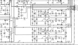
Power transistor emitter collector reversed....
I see all is symmetric Plus Minus wise. Nothing reversed.
For a series regulator there are two ways to do it at the power transistor. Emitter at the load side or collector at the load side.
Collector at the load side is used when looking for Low Drop. This for single or Darlington, another story which Slizar ( pnp + npn ).
the phono preamp and first stage of the amp regulators have the collector at the load, but i'm not sure they did it for low drop reasons...having higher gain makes the ripple lower but that can make the whole regulator oscillate ad that is probably why they used c65,c71, c104,c133
- Home
- Amplifiers
- Power Supplies
- Are you really fine with IC voltage regulators ?