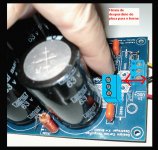
post28 shows Q9 & Q10.
these happen to be located right at the two ends of the Power supply rails. These are the closest that the supply rails come together on the PCB.
Here is where the HF decoupling should be fitted. This is to minimise the length of track/trace from the +ve output device collector to the +ve rail HF decoupling to the -ve HF decoupling to the -ve device collector. This route must be short to keep inductance down. If inductance in this route is allowed to rise then the HF decoupling cannot pass HF transients and becomes worthless.
The centre point of the LF decoupling and the centre point of the HF decoupling are joined together to become the PCB Power Ground. Unfortunately the main Ground is ~90mm away from the HF decoupling centre point. That is brought about by the enormous spacing between the +ve supply rail trace and the -ve supply rail trace. These two rails must be located right next to each other to minimise the radiated effects the half wave rectified currents have on the rest of the low level circuitry.
Okay. I think I understand. That would be tough to implement in this scenario without a double-sided board.
..Todd
..Todd
Wanna be happy?
Build a Dx Blame or build one alike that:
YouTube - GolfJet Jet Turbine Powered Golf Cart
both will provide you fun and strong emotions!
regards,
Carlos
Build a Dx Blame or build one alike that:
YouTube - GolfJet Jet Turbine Powered Golf Cart
both will provide you fun and strong emotions!
regards,
Carlos
Earlier release for the Supercharged soon...the next days
YouTube - Supercharged earlier release...soon
regards,
Carlos
YouTube - Supercharged earlier release...soon
regards,
Carlos
We are working in the details, discussing sizes and shapes
We are not sleeping..the "Corporation" is working full time to achieve better and better quality into boards, layout and schematic.
Soon you gonna see the result..now we are reducing supply size, because our amplifier is suggested to use two separated supplies...also can use a single one too..but when using two supplies the performance is better, but also the room needed to two transformer and two supply boards is huge..so..we are reducing all we can.
regards,
Carlos
Attachments
Last edited:
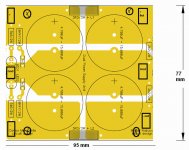
Dear Friends...here you have the Dx Blame MKII Supercharged
and the board.
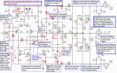
I will soon explain you in details..but you can be watching the schematic and the board and you will understand the basic things.
First.......... schematic is the same..amplifier is the same... sonics is the same..quality is the same..distortion is the same.... power is different
Second....the Supercharged is a 200 watts rms / 4 ohms power amplifier
third...the Dx Blame MKII is a 180 watts amplifier to 3 ohms loads....so....will be good to difficult and low impedance speakers.
You see some parts in the board without value..these are the parts will be replaced depending the model you will assemble.
The board is good for:
Dx Blame ES
Dx Blame ST
Dx Blame MKII
Dx Blame MKII Supercharged
Have only to replace some parts...transistors are the same to all models..yes...all models.
The first three models use 35 o 42 volts supplies
Soon you gonna have more details..also soon you gonna have a group buy to be organized by Mitchel that promissed to do that.
Soon you gonna have black and white layout to allow you to etch your boards at home..not only to Toner transference method, but also to the photographic method to layout image transference to copper boards.
Boards will go with xerox showing part numbers....pdf also will be published...a chart will explain the different parts that belongs to each model in special
So... we are starting to release informations....i will produce texts, also videos explaining the differences..but schematic and board shows things clear.
regards,
Carlos
and the board.
I will soon explain you in details..but you can be watching the schematic and the board and you will understand the basic things.
First.......... schematic is the same..amplifier is the same... sonics is the same..quality is the same..distortion is the same.... power is different
Second....the Supercharged is a 200 watts rms / 4 ohms power amplifier
third...the Dx Blame MKII is a 180 watts amplifier to 3 ohms loads....so....will be good to difficult and low impedance speakers.
You see some parts in the board without value..these are the parts will be replaced depending the model you will assemble.
The board is good for:
Dx Blame ES
Dx Blame ST
Dx Blame MKII
Dx Blame MKII Supercharged
Have only to replace some parts...transistors are the same to all models..yes...all models.
The first three models use 35 o 42 volts supplies
Soon you gonna have more details..also soon you gonna have a group buy to be organized by Mitchel that promissed to do that.
Soon you gonna have black and white layout to allow you to etch your boards at home..not only to Toner transference method, but also to the photographic method to layout image transference to copper boards.
Boards will go with xerox showing part numbers....pdf also will be published...a chart will explain the different parts that belongs to each model in special
So... we are starting to release informations....i will produce texts, also videos explaining the differences..but schematic and board shows things clear.
regards,
Carlos
Attachments
I am also waiting to obtain some DX boards, before I order parts-there is a lot of reading in the DX-ES Blame thread.
For amplifier theory, what books are available that explains vbe and basic amplifier circuits? Soft cover is fine, suitable for reading when waiting to catch a flight!
For amplifier theory, what books are available that explains vbe and basic amplifier circuits? Soft cover is fine, suitable for reading when waiting to catch a flight!
I will love to have you building my amplifiers ASquare
Dear Doggy, books really do not explain such details...forum people may help.... i can do it if you post or mail me specific questions alike; what is VBE, what is the normal VBE, What VBE does.
I will try to find some books for you... send me an email to me to capture your home email adress... then i will be able to send you some tips and tricks, links and so on.
nanabrother@hotmail.com
regards,
Carlos
Last edited:
Hello everyone!
This is the link for the groupbuy:
http://www.diyaudio.com/forums/grou...kii-mkii-supercharged-groub-buy-interest.html
We need to know if there is enogh interest in those PCBs, so please let us know by posting on that thread.
This is the link for the groupbuy:
http://www.diyaudio.com/forums/grou...kii-mkii-supercharged-groub-buy-interest.html
We need to know if there is enogh interest in those PCBs, so please let us know by posting on that thread.
Maybe one of Doug Self's books or else Bob Cordell's new book (see here).For amplifier theory, what books are available that explains ...
Clipping behaviour
Carlos,
Just something I've red on the forum today. Maybe it's not that bad putting a current limiting resistor in the collector of Q6.
My
See post #4 +#5
http://www.diyaudio.com/forums/solid-state/175934-comparison-vas-using-two-transistors.html
Carlos,
Just something I've red on the forum today. Maybe it's not that bad putting a current limiting resistor in the collector of Q6.
My
See post #4 +#5
http://www.diyaudio.com/forums/solid-state/175934-comparison-vas-using-two-transistors.html
You can put it Bensen
This way will be better to you.
I am in a hurry preparing videos and doing a lot of things..but i will think about it...for this board no chance..it is ready..maybe next model...you can cut your board and insert the resistance below the circuit if you want it.
Thank you very much.
regards,
Carlos
This way will be better to you.
I am in a hurry preparing videos and doing a lot of things..but i will think about it...for this board no chance..it is ready..maybe next model...you can cut your board and insert the resistance below the circuit if you want it.
Thank you very much.
regards,
Carlos
The speaker protector board
I am uploading an audio with images to Youtube explaining you some details.
soon it will appear in the signature..down the post.
attached the protector and once again the Dx Blame MKII Supercharged schematic.
Observe was already published the chart...there you have the parts that should be substituted, or replaced, depending the model you decide to build.
regards,
Carlos
Attachments
Last edited:
Here you have Supercharged Release audio in portuguese
I am still producing in English and i will soon post it here:
YouTube - Supercharged lançamento
Latine people are able to understand portuguese
regards,
Carlos
I am still producing in English and i will soon post it here:
YouTube - Supercharged lançamento
Latine people are able to understand portuguese
regards,
Carlos
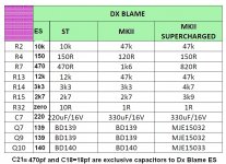
As i told you friends, there are parts that must be substituted, depending
your model choice.
and here you have an image and a chart.
I hope this helps...if you have doubts...please ask here.
Also help me to check if you perceive anything wrong.
regards,
Carlos
your model choice.
and here you have an image and a chart.
I hope this helps...if you have doubts...please ask here.
Also help me to check if you perceive anything wrong.
regards,
Carlos
Attachments
- Status
- Not open for further replies.
- Home
- Amplifiers
- Solid State
- Are you ready to face strong emotions?.. Dx Blame MKII and the Supercharged release!