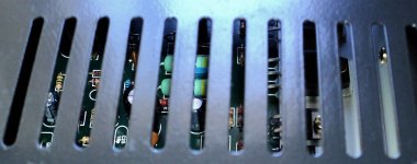
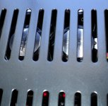
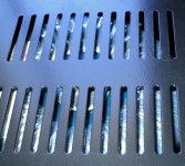
See through the enclosure gaps
boards inside looks nice.
regards,
Carlos
boards inside looks nice.
regards,
Carlos
Attachments
Last edited:
Uncle Carlos,
I'd seen your videos and would like to know more what modifications that you've made.
many thanks in advance
I'd seen your videos and would like to know more what modifications that you've made.
many thanks in advance
Some modifications are result of my own needs
and some of these needs are not standard dear Dexter.
For instance, i do no like too much treble, and some modern audio programs (music) from the Satelite Receiver have too much treble... the equalization is unballanced to my taste...so i have a potentiometer to filter the highs (passive filter, adjustable one... RC filter into the input)...but this depends on the input impedance...or the audio source impedance...there's no good effect if you plug an old Discman (Sony portable CD players) using the low impedance output instead of the line out jack.
Also the 470 ohms (R7) used to increase the amplifier gain was because of this same source....not needed to computers or DVD players that usually have more output level... the standard values are 820 ohms or 1K to R7.
The input capacitor was increased from 1 to 2uF because my own needs also..customized to my needs...of course you can try if you want.... the input capacitor is C1..... my need was to increase power into 5 hertz to be forcing my non efficient woofer to be moving for hours long...and using very low frequency not to bother my own ears or neigthboor's ears.... to "burn in"...to soften the centering spider and the speaker suspension...too much hard to move, needing 30 watts to start to be efficient (550 watts unit).
We cannot listen 5 hertz..so, this does not bothers me or my neighbors.
I have found sonics much better while using 220 ohms to R16... but also i could face once Q6 burned.... bursted, exploded, damaged, when i had loosen ground when using Satelite Receiver...the one uses switching power supply and noises was really huge..not only low frequency hum but also high frequency superimposed that also burned a tweeter (gladly i have a bunch of them to replace while testing and forcing untabilities in the compensation.... well.... during experimentation...or accidents).... because of that i tried 1K... to R16, the original value suggested by Dr. Self...also higher values can be used too, in special if your VAS current is high than the original Dr. Self design or if your supply voltage is higher too... as this results in higher peak to peak swing into the VAS stage.....but sonics, as usual, was hardly damaged...then i decided to revert to 220 ohms and to install a bigger and stronger transistor in the Q6 position..now i am using MJE15032, i have repeated the unstability, a full power and no problems (this time i have disconnected the tweeter.
You see.... all concluded during tests, experimentation and accidents... a real DIY work, a try and error method, having much more much sweat and hard work than deep mathematics knowledge involved.
My compensation capacitor, or Miller if you prefere, was increased because i have not the correct value anymore...so...not to install a bunch of capacitors in paralel i decide to use the bigger one i have..but you see...my own problem, not something standard.
I am using 0.47 ohms as power transistors emitter resistances... this is bad for sonics...good value is 0.22 ohms or even 0.1 ohm.
My " L " shape bracket...the adaptor from the amplifier board to the heatsink resulted no good.... it is not a soft aluminium, not a pure aluminium...also the surface is not polished and the material was submited to an electrolitic treatment to look nice, but result in bad heat transference to the heatsink.... this way, even in standby mode (no signal in the input) i had too much heat (5.7 watts) that warmed the L shape adaptor but did not warmed the heatsink as it should... then, at my home, i have increase the 150 ohms fixed resistance (R20) to 180 ohms...this way my heat during standby is only 2.6 watts....of course dinamically this change the "operation point" and the heat is different when you start from 2.6 watts in place of 5.7 watts)....but you see...once again...because my own problems Dexter.
I do think the videos posted suggest some modifications...and no one of them are harmfull...they are always to your safety... to offer you a more and more reliable amplifier...some modifications where made because i have decided to "take the risk to myself" in the name of better sonics...to keep the 220 ohms resistance is the main one.... i took the risk but i do not suggest you to do that, unless you want to take the risk to yourself too.... your decision.
I do not like or use preamplifier and tone controls..but i will do it..because one amplifier will go to my daugther..and she will connect directly into a DVD output..so, she will need to control tone....and preamplifier will be needed if she decide to use another audio source, as there are different output levels in audio sources...the old tradition of line out standard levels are not obbeyed anymore...you can find 2 volts output in some DVDs.
Each audio system, speakers, audio sources and room acoustics, will need different solutions..you should detect your own custom needs and adjust your amplifier to match your needs...imagine a boomy speaker..a two way very boomy one, these one that uses huge coils in series to the speaker and some condensers connected from positive to negative (10 to 22uf usually) ...in this case you should reduce your input capacitor to 470n or even less, to compensate your speaker..so...sending less bass to your drivers you may have better sound..more balanced sound...so...each case needs some study and adaptative solutions..and these depends on your effort, skills and action.
Standard original schematics you find here:
http://users.tpg.com.au/users/gerskine/dxamp/
and here:
http://www.dx.kinghost.net/
regards,
Carlos
Last edited:
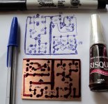
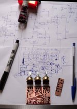
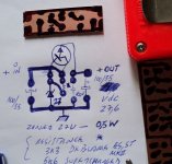
I am producing some prototypes...tone control to my daugthers
an interesting gadget for metering and an electronic step down voltage regulator.
regards,
Carlos
an interesting gadget for metering and an electronic step down voltage regulator.
regards,
Carlos
Attachments

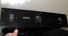
Knobs ordered from China never arrive
Then i have created a new provisory custom model...Semprini Buttoni is the name....hehehe....watch the rubber feets working as volume knobs.
regards,
Carlos
Then i have created a new provisory custom model...Semprini Buttoni is the name....hehehe....watch the rubber feets working as volume knobs.
regards,
Carlos
Attachments
Last edited:

Dx power indicator using two leds to each channel
ready to go...i will wait a couple of days listening to publish the schematic:
YouTube - Dx power indicator, flashing LED sweet gadget
This is the 10 watts (green led) and 100 watts (red led) version... power is rms and at 8 ohms... when the red led goes on the green led goes off because of a feedback action... a multivibrator produces pulses to the red led and also into the green led threshold.
This is powered by audio... sound is rectified and filtered and consumption is 15 miliamperes when red led (and multivibrator) is on..and reduces to 8 miliamperes when the green led is on.
There's a 10/50 watts version too...both tested and assembled... this power is to 8 ohms...if you use 4 ohms speakers, then the power reading will be twice the specified.
Also a low power version was made to 1,2,3 and 4 watts (8 ohms) or 2,4,6 and 8 watts (4 ohms) was made.
It is under test.... by a couple of days....
The most interesting is that you do not need power supply or batteries.... it is powered by audio.... so, you can install it inside a speaker to have monitoring of the power is entering your speaker system.
regards,
Carlos
You have built a voltage indicator, not a power indicator.ready to go...
Also a low power version was made to 1,2,3 and 4 watts (8 ohms) or 2,4,6 and 8 watts (4 ohms) was made.
Nothing wrong with a voltage indicator. Just scale your leds for dBV relative to a reference voltage.
How to install protection blue boards...the auxiliary transformer
YouTube - DX Supercharged Loudspeaker Protection Board
regards,
Carlos
YouTube - DX Supercharged Loudspeaker Protection Board
regards,
Carlos
I've been going through the BOM to put my order together and I can't find C13 & C24 in Mica as recommended, but I can find them in Ceramic is there any harm in this?
These are the ones I'm looking at ordering instead
Digi-Key Part Search
Digi-Key Part Search
These are the ones I'm looking at ordering instead
Digi-Key Part Search
Digi-Key Part Search
Luke:
There you go: Digikey's 338-1042-ND
There you go: Digikey's 338-1042-ND
An externally hosted image should be here but it was not working when we last tested it.
Thanks Mitchell, don't know why I couldn't find them in my search.
My next question is in regards to resistors are there any in the circuit people feel deserve having a bit more spent on them, for example starting at R1 I have options ranging in price from $0.08 for a stackpole electronics one through to $0.42 for a Ohmite little Demon one and this will obviously continue as I go through. So based of that are there some where spending a bit extra is a good idea and some where it will make no difference?
My next question is in regards to resistors are there any in the circuit people feel deserve having a bit more spent on them, for example starting at R1 I have options ranging in price from $0.08 for a stackpole electronics one through to $0.42 for a Ohmite little Demon one and this will obviously continue as I go through. So based of that are there some where spending a bit extra is a good idea and some where it will make no difference?
Luke,
If you want to spend more money on some components, you can use non inductive resistors for the output emitter resistors and also for the zobel and boucherot networks (5W). Besides that, use regular metal film resistors.
If you want to spend more money on some components, you can use non inductive resistors for the output emitter resistors and also for the zobel and boucherot networks (5W). Besides that, use regular metal film resistors.
Luke,
If you want to spend more money on some components, you can use non inductive resistors for the output emitter resistors and also for the zobel and boucherot networks (5W). Besides that, use regular metal film resistors.
I did your suggestion when building my Blame ES. The Wirewound resistors made no difference/loss in sound quality. Buy them and make the same amp and be just as happy. I used ceramic caps as well.
Regards
Niss_man
Any issue with using this as the coil on the amp board Digi-Key Part Search
Hi Niss_Man I see your in Brisbane as well, when I get around to starting this project would you be happy to give me a hand in the final stages testing and setting any of the adjustable values as this is where I lack any experience?
Luke
Hi Niss_Man I see your in Brisbane as well, when I get around to starting this project would you be happy to give me a hand in the final stages testing and setting any of the adjustable values as this is where I lack any experience?
Luke
niss_man said:The Wirewound resistors made no difference/loss in sound quality
That's what I imagined. I don't think the difference is significant, but, there's always the psychological effect 🙂
Any issue with using this as the coil on the amp board Digi-Key Part Search
Hi Niss_Man I see your in Brisbane as well, when I get around to starting this project would you be happy to give me a hand in the final stages testing and setting any of the adjustable values as this is where I lack any experience?
Luke
Certainly Luke. I do have some spare Blame Pcb's looking for a good home as well. For the coil I used some 1mm diameter teflon coated copper wire I had spare and wound it myself.
Regards
Niss_man
Last edited:
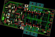
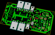
Optional PCB
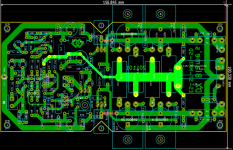
Optional PCB for DX Blame series; ES, ST, MKII, Supercharge. option for 'TMC' too.
NOT BUILDED YET! please double check if you'll use it.
PCB file on KiCad format.
Optional PCB for DX Blame series; ES, ST, MKII, Supercharge. option for 'TMC' too.
NOT BUILDED YET! please double check if you'll use it.
PCB file on KiCad format.
Attachments
Optional PCB for DX Blame series; ES, ST, MKII, Supercharge. option for 'TMC' too.
NOT BUILDED YET! please double check if you'll use it.
PCB file on KiCad format.
That layout "style" has performance written all over it. "wire with gain" style!! 🙂
OS
- Status
- Not open for further replies.
- Home
- Amplifiers
- Solid State
- Are you ready to face strong emotions?.. Dx Blame MKII and the Supercharged release!