it would be great, don't you think?Yes you can use them as digital output’s and also as digital input ie high or low.
I see your point.
alright I went back to my project which me and a friend had built in that a custom PCB was made and I had burnt a uno boot loader so I was using those pins. (may be my Oooops )

As for using nano I completely concur with Zdr.
Other than that
1) Arduino Micro ( 32u4)
2) If we used a decoder than 3 I/0 pin to select 7 or 8 inputs and two I/0 can be used for selection of two output options.
3) I2C i/o expander for selecting relays.
Other than that
1) Arduino Micro ( 32u4)
2) If we used a decoder than 3 I/0 pin to select 7 or 8 inputs and two I/0 can be used for selection of two output options.
3) I2C i/o expander for selecting relays.
Zdr if you could support the software changes then I can work on hardware and share the Gerber's and PCB files with you and we could discuss it.Yes, you can definitely use another MCU which has more ports and processing power, a completely new PCB layout and firmware. But that belongs to a new thread then.
if you want I can participate in the work. in these two days I have been studying how to solve the problem based to yoursZdr if you could support the software changes then I can work on hardware and share the Gerber's and PCB files with you and we could discuss it.
aditya zdr
valuable information
and assuming I have no knowledge of Arduino, I found some info online on how to expand the I / O using a PCF8575 expander connected to a ULN2803 by adding resistors to overcome the problem of driving the relays because the voltage is insufficient and I also added LEDs for signaling the input and output of the various channels. everything must be checked by those who know more than me, see pcd, I can post the gerber file created with Eagle programthe jump between pins 1 and 3 of the voltage regulator U4 - TLV702475, why was it done since pins 1 and 3 are connected to each other on the wiring schematic diagram?Jumper that needs to be placed:
View attachment 855968
ok thanks 👍It's needed because a trace is missing on the pcb.
another question, how come you didn't use cmos, for example CD4051 or CD4052 instead of relays
For audio signal switching? Are you kidding?ok thanks 👍
another question, how come you didn't use cmos, for example CD4051 or CD4052 instead of relays
as much as I agree with you on not using 4051 for audio switching Acram used 51 & 52 for one of its amps ( I do not think anything is better than a relay ) but still 😛 .For audio signal switching? Are you kidding?
I am aware of the leakage things between channels and therefore it's not liked.
nooooooooooo - too much interchannel leakage. Relay gives the best isolation ( as per Me ).. I have seen it on industrial data logger where in we would have issue with certain channel picking up some part of input of other channel sook thanks 👍
another question, how come you didn't use cmos, for example CD4051 or CD4052 instead of relays
Hello,
they use a 328pb Why couldn't I read out here ?, the 328pb is difficult to obtain, the connections PE1 and PE0 are also not used
the 328pb certainly needs another bootloader (minicore) , which one did they use ?
I want to test the project on a breadboard first, and already own normal nano 328p
they use a 328pb Why couldn't I read out here ?, the 328pb is difficult to obtain, the connections PE1 and PE0 are also not used
the 328pb certainly needs another bootloader (minicore) , which one did they use ?
I want to test the project on a breadboard first, and already own normal nano 328p
thanks for your advice.For audio signal switching? Are you kidding?
Also from my point of view it is better to use relays, preferably with silver or gold contacts
I would probably make a different version of this design - I recently went back to using tape decks and realized I don't have a way to do tape monitoring. So, I'm going to ditch a second output and connect the remaining output directly to RCA. This would allow to have 5 inputs and 6th relay to switch between selected source and tape monitor.
Why would you need PB for this design? I am using normal Nano with P variant.Hello,
they use a 328pb Why couldn't I read out here ?, the 328pb is difficult to obtain, the connections PE1 and PE0 are also not used
the 328pb certainly needs another bootloader (minicore) , which one did they use ?
I want to test the project on a breadboard first, and already own normal nano 328p
but sorry ... the three pin connector J18, of which pin 2 (COM) connected to pin 10 of the ULN2003 is not an expansion for a possible other relay? err?Why would you need PB for this design? I am using normal Nano with P variant.
A pleasure. can you send me the Sketche file of the development of this project?
I would like to do some tests to expand the IN and OUT
Thanks
Attachments

Last edited:
It will take a lot of time? I also use Akai GX77 and Revox PR99 tape recorders. With pleasure I will buy a ready-made KIT with a tape recorder monitor and 5 inputsI would probably make a different version of this design - I recently went back to using tape decks and realized I don't have a way to do tape monitoring. So, I'm going to ditch a second output and connect the remaining output directly to RCA. This would allow to have 5 inputs and 6th relay to switch between selected source and tape monitor.
the link in your BOM is a nano PB,Why would you need PB for this design? I am using normal Nano with P variant.
I tried it with a nano P and it works
thank you, that was very kind of you
J18 is for power supply PCBbut sorry ... the three pin connector J18, of which pin 2 (COM) connected to pin 10 of the ULN2003 is not an expansion for a possible other relay? err?
A pleasure. can you send me the Sketche file of the development of this project?
I would like to do some tests to expand the IN and OUT
Thanks
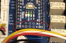
In your picture (#1) you can see PE0 and PE1, and only the atmega328pb has these pinsWhy would you need PB for this design? I am using normal Nano with P variant.
they are unused
Attachments
- Home
- Source & Line
- Analog Line Level
- Arduino+PGA2311 Ultimate PreAmp with OLED and IO switching