I measured it earlier, and after initial wavering results I got -6.85 (with red on E and black on B, 20V setting)
Taking a break now. Cabin fever setting in!
Taking a break now. Cabin fever setting in!
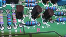
Going back to R115 that we measured earlier. You measured its resistance as 1001 ohms I think, that's fine.
Can you just confirm that you have plus 15 volts on one end and approx plus 6 volts on the other end. All measured with the black lead on chassis.
Something doesn't add up here 🙂
Can you just confirm that you have plus 15 volts on one end and approx plus 6 volts on the other end. All measured with the black lead on chassis.
Something doesn't add up here 🙂
It was reading back and looking at this. Where did the plus 9.4 volts come from ? One end should have plus 15 volts which is derived from a main voltage rail.
Is R115 OK (not gone high or open circuit). I'll have a closer look later but that's the first thing to check. Do it out of circuit i.e. unsolder one end to isolate it before measuring.
I have double checked it both ways. 9.4 and -9.4
I haven't had a chance to desolder one end. Tomorrow afternoon. Sorry, slow progress!
That was taking measurements across it with it in circuit.
Ah, that makes sense now. Well 9 volts and your measured 6 volts of today do add to plus 15.
Just confirm the result and we can move on although I'm struggling to see any scenario that can give the reading you are getting on Q106 just at the moment. I'll have a fresh think tomorrow.
The plus 15 is correct.
We need to find why the other end is low and the reason has to be that current is being drawn... but there is nothing obvious yet in the measurements. Q107 and Q109 emitter voltages show that those two transistors are passing very little.
Its not just that, its also why the amp can seemingly hold the DC conditions at the output correctly with such a massive error within the 'loop'.
I'll think some more tomorrow.
Reading back and you say you changed some caps before finding the shorted rectifier. Try and recap ( lol, not a good choice of words) over anything you have changed and done.
Have any other parts been replaced anywhere ?
One for tomorrow.
Ok, last one for to other, quick summary....
Bought as not working on eBay so I have absolutely no idea what lead to its 'death'
It was instantly blowing internal fuse when powered up.
The first assumed fault was the MOSFETs, these were all replaced. Still blowing.
Then traced fault to rectifier bridge, one of the four diodes, one on right channel had failed and was a short. They were all replaced.
This allowed amp to switch on without blowing the fuse. At this point I thought all was ok.
Then I had problem with right side distortion and cutting out when turned up....
Thanks for your help and patience!
Bought as not working on eBay so I have absolutely no idea what lead to its 'death'
Not knowing the history of something is a very real problem. You just don't know what has gone on or whether any man made faults have been put on there.
Jut thinking aloud...
R115 has around 9 volts across it which translates to a current of 9 milliamps. So where is that current flowing ?
It can only be into Q106 and Q108.
But... there is no current flowing in Q107 and Q109 as witnessed by having -15 volts on the emitter of each. There is no voltage across those 2k7's.
So its not flowing there.
Q108 ? If it were dumping a few milliamps into the driver stage then things would be happening such as excessive quiescent current and high DC offset and its not.
Replace Q108 lets remove it from doubt.
As for the fault, I guess one would assume the obvious and that there was a shorting of the cables on the right channel? Whether this caused the diode to fail or maybe that came first and was the fault, who knows. The seller was not the owner so there was no chain of enquiry open to me.
Its hard to say.
The diode could certainly have been a one off fault on its own... it happens and they aren't massively rated.
A short on amplifier output (the most likely scenario for abuse) would draw high current from the output stage. Those FET's are tough though and could survive something like that while causing the diode to fail through excess current draw.
Faults in the small signal stages are rare, and yet its hard to see this being an output stage issue.
There are further things we can do which might be worthwhile to try and pin this down.
Also, if its been worked on by persons unknown then anything is possible. For example having the amp plugged in but OFF and at the same time touching the circuitry with an earthed soldering iron could cause damage because of the path that then exists between soldering iron tip and chassis ground. In other words you have a 'shorting link' everytime you touch the board.
If the main caps have charge on them then you can cause damage by them discharging through the soldering iron via any low impedance path (transistor junctions).
Lets see what happens first.
Well congrats .. convoluted perseverance paid off.
Did say early on that the Rect Diodes were a fault area 😉.
Now.. that you have the silly thing running.. Have you had a chance to hear just How poor it Sounds?
If not.. you soon will.
Did say early on that the Rect Diodes were a fault area 😉.
Now.. that you have the silly thing running.. Have you had a chance to hear just How poor it Sounds?
If not.. you soon will.

Q108
Ok, replaced and then measured q108
E=6.02
B=5.35
C=2.42
Also measured q106
E=6.02
B=12.76
C=-14.51
So pretty much the same. Headphones still distorted on right.
Ok, replaced and then measured q108
E=6.02
B=5.35
C=2.42
Also measured q106
E=6.02
B=12.76
C=-14.51
So pretty much the same. Headphones still distorted on right.
Last edited:
Its odd.
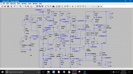
I'm so puzzled with this that I've even thrown the circuit into a simulation so that you can see the expected voltages, and as we keep saying, its around Q106 that is the stand out problem.
The voltage in brackets are your measured readings, the other voltages are the voltages in the working simulation.
Attachments
- Status
- Not open for further replies.
- Home
- Amplifiers
- Solid State
- Arcam Delta 290P keeps blowing fuse