The blue spark only happened once, but it was certainly odd. Has not done that since. But I must make up a bulb test rig.
Although the only old filament bulb I have is a 10 watter!
Although the only old filament bulb I have is a 10 watter!
Last edited:
the mains Halogen bulbs are also tungsten filament and make a good substitute.The blue spark only happened once, but it was certainly odd. Has not done that since. But I must make up a bulb test rig.
Although the only old filament bulb I have is a 10 watter!
I have seen them in 28W and 42W sizes.
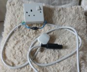
Lol, my bulb tester looks a a lot scarier than that 😀
It might be worth you deliberately forcing a low bias condition on the amp (on both channels) while working on this. That can easily be done by applying a blob of solder across C107. That will disable the auto bias input.
It might be worth you deliberately forcing a low bias condition on the amp (on both channels) while working on this. That can easily be done by applying a blob of solder across C107. That will disable the auto bias input.

The table lamp would put the bulb across L and N in the socket and thus in series with the supply, so yes 
Thanks, it seemed simple but good to get approval! Just watching Grand Prix now. I will then start some testing.
You had mentioned about testing between components and chassis ground. I had requested some confirmation of this, and where is best to connect. It sounds obvious but just wanted to be sure. Cheers.
You had mentioned about testing between components and chassis ground. I had requested some confirmation of this, and where is best to connect. It sounds obvious but just wanted to be sure. Cheers.
Any of the chassis metalwork should be 'chassis ground'. The black meter lead would go there for all the general voltage checks.
OK, first of all, the bulb comes on brighter then dulls down and remains dull, is that OK. Only using a 10 watter.
Next, the measurement across Q106 is not stable. Wavering around from -4.4v to 0.04v (red on E black on B, 20V setting)
Check that, done it again and its stable at -6.85
Next, the measurement across Q106 is not stable. Wavering around from -4.4v to 0.04v (red on E black on B, 20V setting)
Check that, done it again and its stable at -6.85
Last edited:
That sounds OK... to good really for just a 10 watt bulb... however !
First thing is to check the supplies and see they are correct. The -/+44 and -/+15. They may be low with using a bulb, although on the other hand, if they were low then current would be being drawn and the bulb would light.
It is a mains filament type bulb ? and not an energy saver type. It must be a tungsten filament type.
Yep you need to use a bulb with a real filament in it. A CFL or a LED lamp will not work! I have some old 60W and 100W incandescent bulbs i guard jealously for this purpose 😉
OK, yeah 10W is a bit too low. 60W is better. 100W will be OK.
You should get a brief flash as the power supply capacitors charge, and maybe a dim glow if the unit is operating normally. If the bulb gets bright, something is drawing significant current - at idle, the amp should not do that.
You should get a brief flash as the power supply capacitors charge, and maybe a dim glow if the unit is operating normally. If the bulb gets bright, something is drawing significant current - at idle, the amp should not do that.
OK, first set of readings with black lead clamped to chassis, Red probe to legs of transistors, set to 20V. Measured in order E, B, C
Q106 = 5.88, 12.82, -14.52
Q108 = 5.96, 5.15, 2.43
Q110 = 14.16, 13.54, 5.24
And for comparison, on the good side;
Q6 = 13.53, 12.92, -12.41
Q8 = 13.54, 12.94, 2.2
Q10 = 14.25, 13.61, 12.94
Q106 = 5.88, 12.82, -14.52
Q108 = 5.96, 5.15, 2.43
Q110 = 14.16, 13.54, 5.24
And for comparison, on the good side;
Q6 = 13.53, 12.92, -12.41
Q8 = 13.54, 12.94, 2.2
Q10 = 14.25, 13.61, 12.94
Second set; set to 20V. Measured in order E/B/C
Q111 = -0.61, 0.01, 5.34
Q116 = -0.60, 0.00, 12.84
Q119 = -15.10, -14.48, -13.86
Q118 = -14.48, -13.87, -0.59
Q117 = -14.57, -13.92, -14.48
Q109 = -15.06, -14.33, -14.53
Q107 = -15.06, -14.52, 2.41
Q11 = -0.60, 0(?), 12.93
Q16 = -0.60, 0.00, 12.93
Q19 = -15.10, -14.49, -0.59
Q18 = -14.49, -13.88, -14.49
Q17 = -14.68, -13.94, -14.49
Q9 = -13.06, -12.43, -12.42
Q7 = -13.03, -12.43, -1.95
Q11 Base was hard to reach so not sure if this was a true reading
Interesting.
Q106... looking at the measurements it seems like we are saying that replacing that transistor hasn't changed anything.
Is that correct ?
Now we have anomaly in the readings... and the devil is in the detail with this.
Your new reading for Q106 is showing the emitter as the more negative of the two (emitter and base) and a reading anywhere from around 6 to 9 would be possible because the junction is actually reverse biased and breaking down (operating almost like a zener diode) although non-destructively.
It might be worth you checking the result across Q106 to be 100% sure. With the red lead on the emitter and the black on the base you will be seeing minus 7 volts or so.
Let me study the rest of your readings.
Q106... looking at the measurements it seems like we are saying that replacing that transistor hasn't changed anything.
Is that correct ?
Now we have anomaly in the readings... and the devil is in the detail with this.
Lets stick with Q106 just for the moment.
Plus 7.1 volts with the red lead on the emitter and the black on the base ?
If that is so then Q106 is certainly faulty. You didn't mean 0.71 volts ? We have to be very very clear on the readings. If you have 7.1 volts then there is no doubt that the transistor is faulty.
Your new reading for Q106 is showing the emitter as the more negative of the two (emitter and base) and a reading anywhere from around 6 to 9 would be possible because the junction is actually reverse biased and breaking down (operating almost like a zener diode) although non-destructively.
It might be worth you checking the result across Q106 to be 100% sure. With the red lead on the emitter and the black on the base you will be seeing minus 7 volts or so.
Let me study the rest of your readings.
- Status
- Not open for further replies.
- Home
- Amplifiers
- Solid State
- Arcam Delta 290P keeps blowing fuse