So one step at a time.
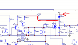
Look at your readings for R113 and R114. You are showing only around 1.6 volts on each end. That is showing that the +44 volt rail is missing to that area of the board.
Look at the circuit.
The 44 volts should be present on both ends of D102 and from there have a direct connection to R113 and R114.
There are really only two possibilities, firstly the diode could be open circuit, and secondly there could be open circuit print (a crack) on the board. If the diode is open you will measure your 1.6 volts on the 'striped' end while having +44 on the other end.
Attachments
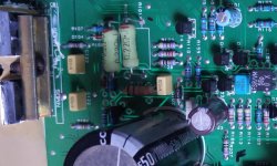
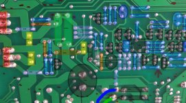
OK, thanks, I have taken some images of the front and back of the PCB and I am going to go away and study this along with the circuit diagram and your last bit of advice, and all that has gone on before and try and get a better understanding of what is going on rather than depending on your (very much appreciated) help all the time.
I should add that there appeared to be damage to the circuit board. Looked carefully under magnifying glass. Also it looked in pretty immaculate condition internally when I got it.
I will come back in due course, although I might not get any time tomorrow.
Thanks
I should add that there appeared to be damage to the circuit board. Looked carefully under magnifying glass. Also it looked in pretty immaculate condition internally when I got it.
I will come back in due course, although I might not get any time tomorrow.
Thanks
Ok, well no further forward. I replaced d102 but I am still getting identical readings.
Out of interest, all three cables from the toroid give 0.00 readings against chassis ground (green and two blue). Seemed odd to a layman like me.
I have been trying to make sense of the readings but nothing obvious is jumping out at me.
Out of interest, all three cables from the toroid give 0.00 readings against chassis ground (green and two blue). Seemed odd to a layman like me.
I have been trying to make sense of the readings but nothing obvious is jumping out at me.
The centre tap of the toroid will go to ground, and the resistance of the secondary windings will be so low that they also read 'short' to ground. So all normal there 🙂
Look at the diagram in post #241. You have to have the +44 volt supply present on the anode (non striped end) of the diode, and the diode cathode should have almost the same voltage present which then feeds off to R13 and R14.
Your previous readings showed the supply missing from R13 and R14. So you need to trace the voltage and see where it is disappearing. If there is no +44 volts on the diode then you have to look further back, tracing the print from the diode to the power supply. The diode anode will end up back at the main reservoir caps (the big 10,000uf ones).
OK, I was doing a bit of tracking, Basically the cathode end of D102 goes to the bank of resistors, R113 etc and it is carrying 1.7 volts. It ends on the top side of the board at a blob of solder underneath R114.
The anode end travels below board to a blob of solder. Take this to the other side and this then follows another track directly to the positive terminal of C201.
I actually measured C201 and C202 earlier and it read 46.2/0.00/0.00/46.2 from left to right, which means C201 positive and C202 negative gave 46.2V
Therefore, between C201 positive and the anode of D102 the voltage drops from +46.2 to 0.00.
It would appear that the capacitors have to connect to the board both above AND below. Perhaps in replacing them I have failed to make this double contact?
Photos to follow...
Last edited:

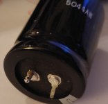
you may have ripped out the through hole plating when you took out the origional caps this is a common event so check
regards trev
regards trev
I am aware of that scenario. It happened on another similar amp. In fact it pulled the whole track up! I will check the original caps and see if they have a little collar around them!
Aha! It's gunna be tricky though making that contact on the track on the top of the board, mmmm, maybe drill a small hole through the board next to the capacitor and run a wire through?
I can't remember at what point you changed the capacitors, it seems so long ago...........
Would be better probably just to wire point to point under the board
Would be better probably just to wire point to point under the board
Last edited:
Yes. I should have tested it properly before fitting the DNM ones.
I then put back a pair from another working 290P after some negative comments about the long connecting wires.
I then put back a pair from another working 290P after some negative comments about the long connecting wires.
Sounds like you are onto something. Preferred (neatest) repair option would be to drill the board and make the connection manually. Another option is to scrape the laquer off the print and add a few strands of copper wire through the hole neatly soldering onto both sides of the board. Then fit and solder the caps.
If you go back to post 247 and the right hand image taken whilst I had the caps attached to the long leads. The reason for the leads was that C102 and R58 were in the way of larger diameter caps.
However if I reduce the leads to only about 1 or 2 cm then that would hopefully not be long enough to create any "inductive resistance" issues that were mentioned before, but it would allow me enough room to solder the lead both above and below the board, thus resolving my problem, hopefully!
However if I reduce the leads to only about 1 or 2 cm then that would hopefully not be long enough to create any "inductive resistance" issues that were mentioned before, but it would allow me enough room to solder the lead both above and below the board, thus resolving my problem, hopefully!
Last edited:
If it is only those two components stopping the replacements fit then could you perhaps remove and refit those parts on the underside of the board ?
Hmmm, an interesting prospect considering I am taking it out of its original metal casing anyway. I would need to know everything was good first though.
A good idea. so long as I can ensure it still makes proper connection from the underside.
Is this because you think the short length of cable may still have an effect? I may email Denis at DNM and see what he thinks.
A good idea. so long as I can ensure it still makes proper connection from the underside.
Is this because you think the short length of cable may still have an effect? I may email Denis at DNM and see what he thinks.
- Status
- Not open for further replies.
- Home
- Amplifiers
- Solid State
- Arcam Delta 290P keeps blowing fuse