Ongoing...
Ok, I replaced capacitors with original type that were taken out of a working 290P.
I have checked all my work and it looks fine.
One thing that crossed my mind is that i may have at one time put the board back in the case without trimming the MOSFET legs on the underside of the board. I would however have thought this would have been something i would have noticed either visibly or audibly? No sign of damage. Otherwise not sure where to go next. Maybe i can recheck MOSFETs. Can this be done under power?
I have invested in a pair of spring clip probes for my multimeter. Just arrived before the weekend.🙂
And just to confirm, with left channel only connected to speakers it drives it perfectly, bi-wired via left SP1 and left SP2. Fails to drive e through right. Just getting faint distorted sound (i did not increase volume to the point where the amp cuts out as it doesn't sound to healthy for the speaker).
And headphones still very distorted on right.
And headphones still very distorted on right.
Last edited:
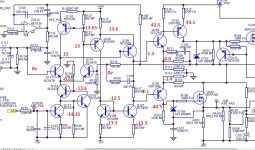
The first thing is to find out why there is zero volts across R117
You are going to have to do careful voltage measurements and record the results. That hopefully might give a clue.
So for initial testing, what have you across:
R180 (0.7)
R118 (2.4)
R119 (2.4)
R126 (1)
R127 (1.6)
R115 (1.8)
The numbers in brackets are the approx voltages I would expect.
You are going to have to do careful voltage measurements and record the results. That hopefully might give a clue.
So for initial testing, what have you across:
R180 (0.7)
R118 (2.4)
R119 (2.4)
R126 (1)
R127 (1.6)
R115 (1.8)
The numbers in brackets are the approx voltages I would expect.
More Measurements
OK, some odd ones here...
Multimeter set at 20 V
I assumed polarity wasn't an issue...
R180 = 0.62
R118 = 0.00
R119 = 0.00
R126 = 0.92
R127 = 1.52
R115 = 9.39
OK, some odd ones here...
Multimeter set at 20 V
I assumed polarity wasn't an issue...
R180 = 0.62
R118 = 0.00
R119 = 0.00
R126 = 0.92
R127 = 1.52
R115 = 9.39
Is R115 OK (not gone high or open circuit). I'll have a closer look later but that's the first thing to check. Do it out of circuit i.e. unsolder one end to isolate it before measuring.
Q106 could also cause this. Make 100% sure you haven't accidently blobbed solder across anything around there while working on it previously. Particularly across base and emitter which would turn of Q106 and give these symptoms.
I have double checked it both ways. 9.4 and -9.4
I haven't had a chance to desolder one end. Tomorrow afternoon. Sorry, slow progress!
I haven't had a chance to desolder one end. Tomorrow afternoon. Sorry, slow progress!
That's OK.
Its an ohms test across the resistor that we want (amp off, one end unsoldered).
Its unlikely tbh that a part like that would fail at the same time as the other issue you had, more likely is something untoward that has happened. Only you know exactly what has/has not been done but certainly that resistor and Q106 would give the symptoms you have.
That's spot on.
Your voltage readings give some big clues, specifically zero volts across R118 and R119.
Q106 is a common factor in all that (and the resistor you have just checked). Don't discount something like a solder blob. If you have carried solder on the iron over the PCB then some could have fallen onto the board. It does happen.
I can't really see anything else around there that could give these symptoms. You have no bias current and the DC offset is being held correctly. Most faults would not do that and would either cause obvious destruction or put out some massive DC offset.
Look the board over closely. If you still can't see anything then we continue with some more voltage checks around Q106. The voltage across the base/emitter junction could be a good clue. It should be around 0.65 volts with the emitter the more positive of the two.
One for another day ?
OK, I am pretty sure there are no solder splashes or blobs.
When you say "The voltage across the base/emitter junction could be a good clue. It should be around 0.65 volts with the emitter the more positive of the two" where is this being measured?
When you say "The voltage across the base/emitter junction could be a good clue. It should be around 0.65 volts with the emitter the more positive of the two" where is this being measured?
Its across the actual junction. If you look at the circuit, the emitter goes to R115 and the base to R122. So it is the voltage between those points. With the red lead on the emitter and black lead on the base you should see around 0.65 volts.
I've had a good look at the circuit and I can't really see anything else (as a single component fault) that would give your problem
And I know that I keep going back to the original problem (the bridge rectifier) because that was so definite an issue and there should be no consequential damage from that.
If you still can't find anything amiss then the next step would be to record and then pencil in the voltages of all the transistor nodes onto the diagram. Seen like that and something may jump out as being amiss. Its only 5 minutes work to do that, with all voltages being measured with respect to chassis ground.
I'll look in again tomorrow.
If you want to record the voltages then just initially write them down in the form:
Q111
E=
B=
C=
Q118
E=
B=
C=
And so on.
If you want to record the voltages then just initially write them down in the form:
Q111
E=
B=
C=
Q118
E=
B=
C=
And so on.
OK, thanks once again. I was getting interrupted to much with work emails and so I think I will have to leave it until tomorrow again. I have put R115 back into circuit. I will check those that you mention.
I will try to start earlier in the afternoon if I get enough peace from work. The daylight is easier to work in anyhow.
I will try to start earlier in the afternoon if I get enough peace from work. The daylight is easier to work in anyhow.
Q106
In advance of testing....
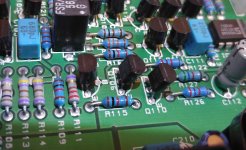
OK, so measuring between Q106 and resistors.
Q106E to R115(which side)
Q106B to R122(which side)
Power on with input connected on minimum volume setting.
Speaker selectors switched on.
I have attached a photo of Q106 and surrounding components (R115 in foreground and R122 behind to right)
cheers
In advance of testing....
OK, so measuring between Q106 and resistors.
Q106E to R115(which side)
Q106B to R122(which side)
Power on with input connected on minimum volume setting.
Speaker selectors switched on.
I have attached a photo of Q106 and surrounding components (R115 in foreground and R122 behind to right)
cheers
Attachments
Last edited:
- Status
- Not open for further replies.
- Home
- Amplifiers
- Solid State
- Arcam Delta 290P keeps blowing fuse