![IMG_20231204_152951[1].jpg](/community/data/attachments/1150/1150347-fddc08851b187d9be1ff46e68225574b.jpg?hash=_dwIhRsYfZ)
![IMG_20231204_153116[1].jpg](/community/data/attachments/1150/1150348-ee490a0e51388b230dd6f6650e00e6ca.jpg?hash=7kkKDlE4iy)

It is okay to do so. But better colling Air moving is If you drill holes in the buttom plate too.I hope the vents are enough. If the temperature is rising, i put a fan with temperatureswitch in. the second way..i ask a friend of mine to built a new top plate with cnc.
Like here
![IMG_20231204_172658[1].jpg](/community/data/attachments/1150/1150391-c0928a314cd024006aacf383d2a2a972.jpg?hash=wJKKMUzQJA)
Hi Chris,
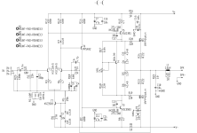
for FH9 i will test IRFP240/9140 shown in this thread https://www.diyaudio.com/community/...-irfp240-irfp9140-and-irp340-irfp9240.400310/
Pairing IRFP140/9140 are to similar to IRFP240/9240. To asymmetrical in my opinion.
I dont know better where to post it...
for FH9 i will test IRFP240/9140 shown in this thread https://www.diyaudio.com/community/...-irfp240-irfp9140-and-irp340-irfp9240.400310/
Pairing IRFP140/9140 are to similar to IRFP240/9240. To asymmetrical in my opinion.
I dont know better where to post it...
first FX8 will be updated. 😉
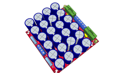
i´ll keep the rectifier and just change the old CRC to the new Cap bank.
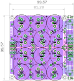
i have got the cap bank pcb by prasi too but i have no 2200µF (16mm diameter) caps to use this nice PCB
i use the Q17_1.0.6 pcb from the Q17 fans. This is not a CRC.
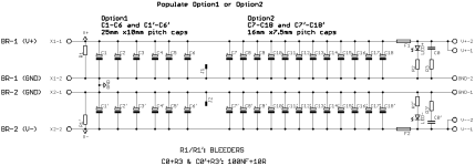
please read the comments on the schematic about the different rectifier and usage of the caps.
i use 2x33mF per rail...therefore i will add a bleeder resistor
kr
chris
i´ll keep the rectifier and just change the old CRC to the new Cap bank.
i have got the cap bank pcb by prasi too but i have no 2200µF (16mm diameter) caps to use this nice PCB
i use the Q17_1.0.6 pcb from the Q17 fans. This is not a CRC.
please read the comments on the schematic about the different rectifier and usage of the caps.
i use 2x33mF per rail...therefore i will add a bleeder resistor
kr
chris
Attachments
Attachments
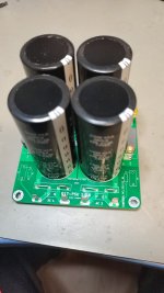
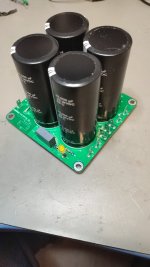
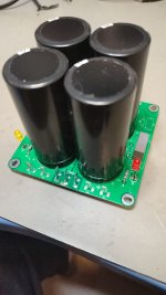
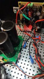
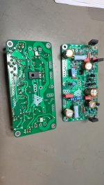
first FX8 updated and mounted. as you can see in the back ground i use as input cap a big foil cap WIMA 22µF MK4 and i changed the gain with R11/R12 back to lower gain 26db .
at the pics you can see the implementation with the 10k 3W Bleeder resistors solders at the "output " of the cap bank as low as possible to use the connectors.
at the pics you can see the implementation with the 10k 3W Bleeder resistors solders at the "output " of the cap bank as low as possible to use the connectors.
Attachments
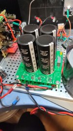
the first FX8 is now ready. Gain is about 26,45dB each channel. new input cap- i found this 22µF Wima monster.😉
measurements.
DMM:
voltage without amps 33,36V each rail
with amps (750mA bias) 30,33V
scope:
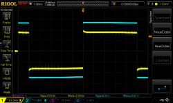
100hz square 140mVrms into 4R
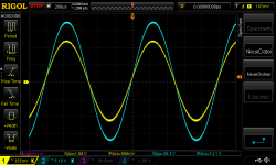
1khz max input without clipping 580mVrms --> about 37WATT into 4R
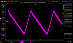
ripple voltage (idle-bias is set as 750mA) cap ban is 2x33mF each rail.--about 181mVrms...i have a lot of noise with my lab lights🙁
listening session in the next few days...
enjoy
measurements.
DMM:
voltage without amps 33,36V each rail
with amps (750mA bias) 30,33V
scope:
100hz square 140mVrms into 4R
1khz max input without clipping 580mVrms --> about 37WATT into 4R
ripple voltage (idle-bias is set as 750mA) cap ban is 2x33mF each rail.--about 181mVrms...i have a lot of noise with my lab lights🙁
listening session in the next few days...
enjoy
Attachments
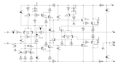
hischematic and Spice file
please help
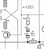
with looking at other threads i wonder if the cap C4 at the schematic FX8 is correct . plus vs minus?!?
in line ups new amp (Cello)...btw...an excellent thread to learn...too much for me but its very good from all experts there !! thx
cello
and at, AA14, FH9 and at AX14 there is the cap other way round.
Attachments
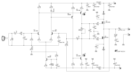
Hi Chris,
i took a look. I can see no difference FX8 to FH9 exept the sizing. In the schematic of the Blame ST/DX amp the capacitor has the same direction. Only the AA14 is different because of the resistor R5 coming from input, i think. If there any trouble with this "C" ? Perhaps its possible to use a bipolar type... or two capacitors. The FX12 has this conclusion too.
I dont think there is a mistake. If you have a look at the first FX8 Apex schematic the capacitor has the same direction.
I have soldered normal Wima100 nf capacitors on the FH9 board. Its possible...🙂
My built of the FX8 stops a little bit. I ordered a bigger SMPS. The 300 Watt Connex has only 2000 µf per rail in the output. Thats to close to the 940 µf per rail of the FX8 in my opinion. I will have the same problem with the Blame ST/ MKII Supercharged. I will change to the 500 Watt Connex with 4700 µf per rail.
Greets
Pedda
Attachments
oops...you are right..FX8 and FH9 are the same... but all other topologies look for me similar and the cap is polarity changed...
hmm..
hmm..
hi
please help
with looking at other threads i wonder if the cap C4 at the schematic FX8 is correct . plus vs minus?!?
in line ups new amp (Cello)...btw...an excellent thread to learn...too much for me but its very good from all experts there !! thx
cello
and at, AA14, FH9 and at AX14 there is the cap other way round.
Polarity of C4 depends on LTP - are they NPN or PNP.
Said that, in perfect world C4 should be bipolar.
- Home
- Amplifiers
- Solid State
- APEX FX8 bimo mod