Chris, sorry...that was my mistake. A NTC is no varistor....you are right.
I first try the original pcb by bimo. On my pcb there is a little mistake. I have to change 2 things in KiCad. The first is to change the space for the input capacitor. The second is to use other, smaller driver heatsinks. I think that gives an little more space and a smaller layout.
Perhaps you know about the "Blame ST" ? I changed the layout a little for four times. Now it is finished.
On my PCB you can built the ES and Blame ST. The driver heatsinks on the pcb are gone. The drivers are together on the output heatsink. With two layers on the pcb its possible. Another amp to test 🙂
The FH9 follows....
Peter

Hi Peter,
no problem.
i do not know about Blame ST. and what do you mean?
PS: my 2nd FX8 is nearly ready...no magic smoke just warm up check temp. voltages and bias...then measure the gain once again.
the gain is about 26,7dB each channel as original set by bimo.
have fun
kr
chris
no problem.
i do not know about Blame ST. and what do you mean?
PS: my 2nd FX8 is nearly ready...no magic smoke just warm up check temp. voltages and bias...then measure the gain once again.
the gain is about 26,7dB each channel as original set by bimo.
have fun
kr
chris
Hi Chris,
you can take a look here https://www.diyaudio.com/community/threads/dx-blame-st-revisiting.245078/
It seems to be a beautiful amp. The first idea was the DX amp, designd by Carlos, Destroxyer X. The Blame ES/ST was built later with help from other users here and the sound must be very good. I will built this Blame ST Amp. I want to hear if it is rearly true.
Unfortunately Carlos died a few weeks ago. RIP
In some case a better idea needs a new or changed layout. The first layout of the Blame was over 100 mm. So i changed to 98 mm in a new layout, saving a little bit money . The little capacitors had not enough space to the big ones and so on. That are reasons i have changed the layout for four times.
With every using of Kicad i get a little better. Not perfect, perfect enough to me...its for fun..hobby...
Congratulations to your second pair of the FX8 ! Have fun with your amps and your music.....
Greetings
Peter
Hi peter...
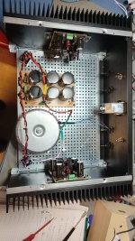
here it is the FX8 muse edition 😉
finally i changed the bleeder from22k to 2x22k in parallel because 99mF are long to loose current with just 22k 🤣
the gain is about 26,6dB and the amps works fine...i will run in and do some measurements.
power is the same as the other....ripple i have to check.
in the afternoon i will have a compare test with the other FX8.
yes there are a lot of interesting amps to build...yes it is a fantastic hobby!
i have to finalize the AA14.
FH9
VSQCA
HEC amp
...😎
Attachments

Last edited:
I think so too...yes there are a lot of interesting amps to build...yes it is a fantastic hobby!
Your amp is looking very nice to me...thumbs up...
Is there a difference in the sound by changing something at the input as you do ? I have got 10 µf CCB caps, really big ones 🙂 i dont know if there is really a difference to a smaller Wima. Is there a differance between Muse or Roederstein foil capacitor ? I dont know....
You will test it to get a result...👍
The FH9 Prasi/XRK mod such as this ?
Peter
Attachments
![IMG_20231110_153537[1].jpg](/community/data/attachments/1147/1147651-d4f8028b9e4ba23937734a0bece73c26.jpg?hash=1PgCi55Loj)
Hi Peter
thanks for your roses..
caps is normally good if you chose some foil or i like the green nichicon bipolar muse.
in my muse edition i use the nichicon UKZ (=muse). will see. but the difference is marginal.
yes this FH 9 is also in my pcb box...waiting for build 😉
my proposal is to change to N ch IRFP140 and the P ch 9140
i try it at my ACA premium...nicer sound..
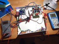
Testing the first pcb. By setting the pot to 250 Ohm i got over 10 Volt in each rail, measured over the testing resistor. Switched off and regulated a bit for three, four times. The voltage is following the pot. At 992 mV, for about 15 minutes, i switched off now, because its a testing heatsink and not the finally. The temperatur was rising to 40 degrees C. Thats ok i think, the heatsink is not big, for testing big enough. The second pcb must follow...
Greetings
Peter
Greetings
Peter
Attachments
as i understand you set instead of the fuse a resistor to measure the current. what value has this resistor?
I = u/ R.....0,99V/?
your supply is 10V each rail...that is ok for the first test.
I = u/ R.....0,99V/?
your supply is 10V each rail...that is ok for the first test.
Hi Chris,
the resistor is 10 Ohm/3Watt. No 2 watt at home...
I have solderd the resistor over the fuseholder, yes. Thats easyer to handle for me. If i get 1 volt its 100 mA on the rail.
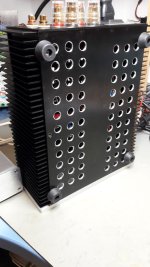
My case has been delivered...on that heatsinks i can finally adjust the bias. I wonder how high i can go with normal heating...
Perhaps my first Class A ?
Peter
the resistor is 10 Ohm/3Watt. No 2 watt at home...
I have solderd the resistor over the fuseholder, yes. Thats easyer to handle for me. If i get 1 volt its 100 mA on the rail.
My case has been delivered...on that heatsinks i can finally adjust the bias. I wonder how high i can go with normal heating...
Perhaps my first Class A ?
Peter
Attachments
![IMG_20231129_171050[1].jpg](/community/data/attachments/1148/1148211-f75dca81112c3d4691e9ea9b23d9153d.jpg?hash=913KgREsPU)
ok...yes with 10ohm it is okay...but you have to remember that the other part of the amp is also drawing current...some mA.
heatsink:
i use for "better" cooling of the MOSFET instead of a big washer a small heat sink before the screw gets in.
e.g. this
you have to use the thermal paste !! use not much of the paste - just a small film - but move the isolator on the heat sink so that you have good thermal contact. the same with all other components. dont forget the isolator for the screw!
use a good ceraterm or ceramic isolator.
temperature over 65°C on the MOSFET should be avoided. -about 30-35W each MOSFET the most guys wrote is enough.
so in my case i have 31Volt with 0,75A bias = 23,5WATT electrical dissipation.
if i built my ACA premium i use also a China housing..but i drilled a lot of hole to get a better konvection.
heat of 48W each side !!! 24V 2Abias
for fast putting into operation i use this heat sink: cheap and 0,65K/W 15Euro heat sink 0,65K/W
heat of 48W each side !!! 24V 2Abias
for fast putting into operation i use this heat sink: cheap and 0,65K/W 15Euro heat sink 0,65K/W
Attachments
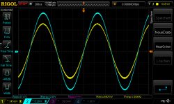
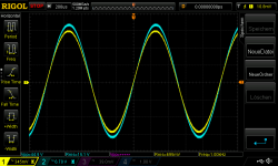
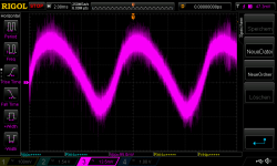
measurements at muse edition (CRC 33mF, R2x0,22E, 33mF, 33mF):
pic 2 700mVrms input 26,7dB gain in 8R, about 28WATT rms
pic 1 600mVrms input 26,7dB gain in 4R, about 41WATT rms
pic 3 is ripple voltage about 70mV
ripple calculator: ripple calculator
current for both channels
fequency is 100hZ because of the rectifier
cap: in FARAD - remember that every elco cap can have 20% less
result is the ripple voltage.
Attachments
I know and she is there. I take the rest away with q-tips 🙂 i hate that grease....i will take ceramic isolation in the end, not for the testing yet.you have to use the thermal paste !!
Can you hear a difference to your muse edition and the normal FX8 ?
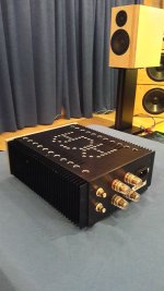
Your ACA Amp looks fine. Nice work...
My case have vents in the groundplate and on topplate. I hope thats enough convection...
In the last amps i built, i set a noctua fan with thermoswitch, 55 degrees. The voltage for the fan is set to 9 Volt by a LM317. You can't hear it. The backplate has little space to the housing. The warm air can get out there.
Greetings
Pedda
Hi Peter,
i did a short listening test and i have to say that the sound is very similar but the better CRC filter is the trick.
the sound is more darker, and what i missed was that a piano has feet and the humans too....strange to read i know, but if i want to listening i need this "floor"
this week i will do some other listening tests and then i plan the upgrade the CRC of the first FX8 too.
then the comparison is fair.
Last edited:
I was a little bit busy...the second board is running without problems. So i built in...but i have to wait for deliveries again. Other Heatsinks for the drivers, ceramic isolators and so on....
But today i finished so far with all cables. In the next step i have to change the driver-heatsinks and adjust final bias...
Greets
Peter
But today i finished so far with all cables. In the next step i have to change the driver-heatsinks and adjust final bias...
Greets
Peter
Attachments
![IMG_20231204_103126[1].jpg](/community/data/attachments/1150/1150267-445ac86854cff9f23539c992ff6f2f56.jpg?hash=RFrIaFTP-f)
![IMG_20231204_104118[1].jpg](/community/data/attachments/1150/1150268-24fde40bf3341b6f65a93e0be8fe9f0a.jpg?hash=JP3kC_M0G2)
My PCb for CRC for the first FX8 is on the way....jlcpcb wrote its in Amsterdam....so it is over the sea😉
Thank you very much.....
I am waiting for delivery von jlcpcb too. The unusuale higher traffic makes trouble to the netherland customs. It's christmas time 🙂
I am waiting for delivery von jlcpcb too. The unusuale higher traffic makes trouble to the netherland customs. It's christmas time 🙂
- Home
- Amplifiers
- Solid State
- APEX FX8 bimo mod