Yes...for Sure.
I Like the scalability
If you ready some pages them you can Set an AB AMP with 100 top 400 mA bias...
Or
Like xrk971 did with 24 v and 1.3 A bias a class A AMP.( 4u 400 mm housing recommend)
DC Offset ist between 0 and 2 mV toggling....perfect
It was my mistake.
I use at my FG ch2 and but i used C1 gnd and Clip there the probe gnd.
That was a Bad gnd Connection..dont ASK ne why i did that
Kr chris
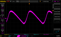
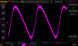
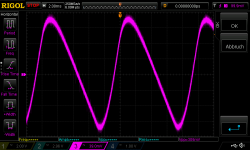
To be sure that the amp is stable with caps in parallel with 4,45Rload i did some measurements.
210mVRms give me about 10Watt. i use square wave and connect a 100nF , 220n F (and just for fun a 680nF) film cap in parallel to the load.
i am not an expert, but i think this amp is stable. little overshoot but no ringing at all.
kr
chris
210mVRms give me about 10Watt. i use square wave and connect a 100nF , 220n F (and just for fun a 680nF) film cap in parallel to the load.
i am not an expert, but i think this amp is stable. little overshoot but no ringing at all.
kr
chris
Attachments
-
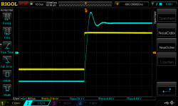 31Vrail_R_Ch_210Vrms 1khz_in_4_45R_C680nF_square_10Watt.png15.1 KB · Views: 76
 -
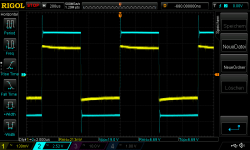 31Vrail_R_Ch_210Vrms 1khz_in_4_45R_C680nF_square_10Watt_2.png18.3 KB · Views: 81
 -
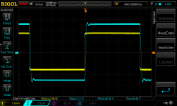 31Vrail_R_Ch_210Vrms 10khz_in_4_45R_C100nF_square_10Watt.png16.3 KB · Views: 80
 -
 31Vrail_R_Ch_210Vrms 10khz_in_4_45R_C220nF_square_10Watt.png17.1 KB · Views: 69
 -
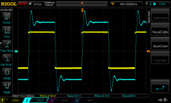 31Vrail_R_Ch_210Vrms 10khz_in_4_45R_C680nF_square_10Watt.png18.8 KB · Views: 77
 -
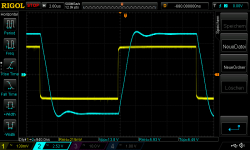 31Vrail_R_Ch_210Vrms 50khz_in_4_45R_C100nF_square_10Watt.png17.2 KB · Views: 69
 -
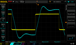 31Vrail_R_Ch_210Vrms 50khz_in_4_45R_C220nF_square_10Watt.png18.2 KB · Views: 69
 -
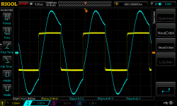 31Vrail_R_Ch_210Vrms 50khz_in_4_45R_C680nF_square_10Watt.png20.9 KB · Views: 66
 -
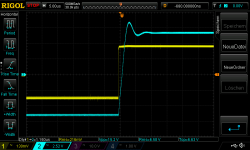 31Vrail_R_Ch_210Vrms 1khz_in_4_45R_C220nF_square_10Watt.png15.3 KB · Views: 76
 -
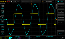 31Vrail_L_Ch_210Vrms 50khz_in_4_45R_C680nF_square_10Watt.png19.9 KB · Views: 63
 -
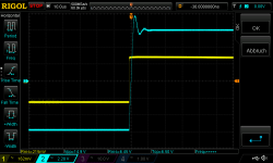 31Vrail_L_Ch_210Vrms 1khz_in_4_45R_C220nF_square_10Watt.png13.4 KB · Views: 75
 -
 31Vrail_L_Ch_210Vrms 1khz_in_4_45R_C680nF_square_10Watt.png14.8 KB · Views: 64
 -
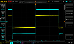 31Vrail_L_Ch_210Vrms 1khz_in_4_45R_C680nF_square_10Watt_2.png16.1 KB · Views: 68
 -
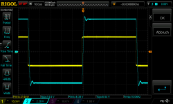 31Vrail_L_Ch_210Vrms 10khz_in_4_45R_C100nF_square_10Watt.png14.6 KB · Views: 74
 -
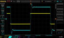 31Vrail_L_Ch_210Vrms 10khz_in_4_45R_C220nF_square_10Watt.png15.9 KB · Views: 74
 -
 31Vrail_L_Ch_210Vrms 10khz_in_4_45R_C680nF_square_10Watt.png17 KB · Views: 63
 -
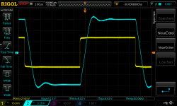 31Vrail_L_Ch_210Vrms 50khz_in_4_45R_C100nF_square_10Watt.png17 KB · Views: 59
 -
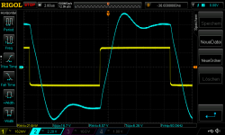 31Vrail_L_Ch_210Vrms 50khz_in_4_45R_C220nF_square_10Watt.png17.9 KB · Views: 70
i think i am old and stupid 🙄Gain:
i matched the input BJT KSC1845 as high hfe as i can get from my batch. but 31dB is 4dB more then XRK wrote in post 7395:
Gain setting ...27dB
as i wrote i set the gain down with R11 and R12 550R and 20k.
could that be that the huge hfe at the input bjt transistors?
no sound check up to now.
🤣
because the gain level is set by R11/R12 and original its 1K/22k so its 22= 27dB.
if i read carefully xrk want to use higher setting - so get the gain high. he used 550/20k = 31db as his other amps.
he want to have 31db as his other amps.
so it is a miss interpretation from my side !!!
i keep this setup with 31db and if i had the amp build ready i will have listening session, then i will change the gain.
Last edited:
You could install a switch to select "summer bias" or "winter bias"! 🙂Yes...for Sure.
I Like the scalability
If you ready some pages them you can Set an AB AMP with 100 top 400 mA bias...
Or
Like xrk971 did with 24 v and 1.3 A bias a class A AMP.( 4u 400 mm housing recommend)
DC Offset ist between 0 and 2 mV toggling....perfect
It was my mistake.
I use at my FG ch2 and but i used C1 gnd and Clip there the probe gnd.
That was a Bad gnd Connection..dont ASK ne why i did that
Kr chris
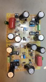
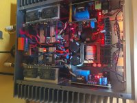
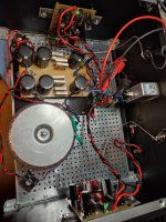
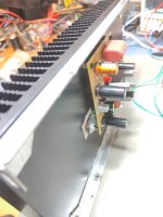
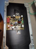
Housing ready. modushop 4U 300mm.
i think a 3U 40mm gives me more head room for installation and looks also nice.
..no magic smoke
CRC is a very old 10mF, 10mF 4x0,47R 10mF per rail just to switch on the amp.
300VA 24VAC sedlbauer - is enough
i have a bias of 420mA and i got 32,7V on the amps.
power ist about 30W on 8R, 40 Watt At4R
enjoy
chris
Attachments
-
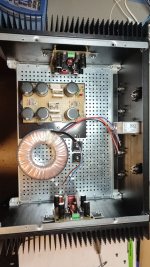 Amp build_9.jpeg215 KB · Views: 123
 -
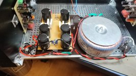 Amp build_10.jpeg181.4 KB · Views: 103
 -
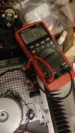 Amp build_bias setting.jpeg133.9 KB · Views: 114
 -
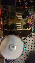 Amp build_CRC.jpeg144 KB · Views: 106
 -
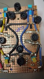 Amp build_CRC_2.jpeg208.3 KB · Views: 107
 -
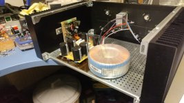 Amp build_8.jpeg149.1 KB · Views: 109
 -
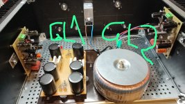 Amp build_7_rectifier planning.jpeg273.4 KB · Views: 111
 -
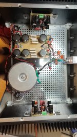 Amp build_6.jpeg205.8 KB · Views: 123
 -
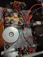 Amp build_5.jpeg433.4 KB · Views: 94
 -
 Amp build_4.jpg611.7 KB · Views: 97
 -
 Amp build_3.jpg276.5 KB · Views: 112
 -
 Amp build_2.jpg358.9 KB · Views: 112
sound check on my chian...ps audio DAC - Nuvista 600 as pre KEF R7
pro:
sound is amazingly "open", very neutral and clear.
i know the lateral MOSFET from a F5 clone but here are the laterals very open, this amp give a very nice sound stage and give you the feeling of a bigger amp (like my Nuvista 600). he plays very smart and vocals and instruments are very good separated. the sound stage is deep!
cons:
very neutral, sometimes nearly too hard
bass is very controlled but could be little bit deeper.
sometimes very neutral, that means if you have a bad recorded track then you will hear that
generally i will recommend to build this wonderful sounding amp.
thanks you mister Mile and Bimo mod for that amp, and XRK for the idea (years ago) to build this amp
enjoy
chris
Last edited:
for compare the different amps i build a Muse edition => parallel 10µ BP muse nichicon as input cap.
and all other caps are Ukz nichicon 470µF.
gain setting will be 27dB not as the other amp 31dB.
amp not ready... 😉
and all other caps are Ukz nichicon 470µF.
gain setting will be 27dB not as the other amp 31dB.
amp not ready... 😉
Attachments
Hi,
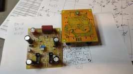
i building the Bimo Mod FX8 too. But not tested yet. Are you sure with setting the input Capacitor to 3,3 µf ? Perhaps thats the reason to get a smaller bassoutput.
I have build the Mini Crescendo from Elektor with the old lateral mosfet. The newer Sk1058/SJ162 are very similar to the old mosfet. Surely, i made changes to get the Mini Crescendo very stable. I changed the input transistors to 2sc 2240/2sa 970 exept BC550/560, Mje 340/350 instead of the BF types and at last the zobel capacitor from 22nf to 100 nf. But i did not change something at the input filter. The Mini Crescendo has a very warm sound over all frequencies.
Im not an elektronic technican and my english is not very good, but i think the input capacitor has to be a large, high quality capacitor for blocking DC and controlling low frequency roll-off. I dont know much about input filters, dont ask me...: ) i wonder why you have changed to 3,3 µf. The normal FX8 from Apex has a 10 µf too in the input...for testing i use a 10 µf bipolar capacitor...
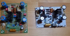
I dont like the Bimo Board with the transistors on the side...i have made an new layout with Kicad....wish it will run...
Best regards
Peter
Attachments
Hi Peter,
Fine that you are try the FX8 too. yes i know that the roll of is with the 3,3µF little bit less then with 10µF. but i want to use the first time this panasonic 3,3µF/450V .
i have no problem with transistors on the side.
Because if you mount the amp pcb on the heat sink i can handle it better then your version. it should not be mechanical force on the solder joints!
finger cross that you design will work. good luck
C1 10µF / R3 22k are 0,7HZ fg
C1 3,3µF/ R3 22k are 2,19HZ fg
chris
Hi gannaji
Did you got some PCB?
kr
chris
sound check at the weekend:
i am still happy with the sound but i want to twiggle around.
so i set the bias current to the max what i guess it is possible with a 4U/300mm housing.
the setup is 810mA.
after 80minutes i check all current and voltage. and for sure the temperature.
MOSFET temp: 69-72°C...for me max temp.
heat sink about 45°...its enough
my power supply - the cheap CRC (10mF,10mF, 4x0,47R, 10mF) sag about 1,5V to a value of 31,2Volt each rail.
DC offset is about 2-5mV at the channels so very good.
the sound gets a bit more "golden" (saxophones are more "sexy") and the vocals have more "chest".
i know that the personal preferences are subjective but it sounds better for me . but some vocals are not just the mouth now it is better. the vocals get more "body". the bass and treble are still excellent and as good as tested with the chain of my brother.
the dynamic -differences between quiet and loud passage are still fine, a bit less then with 400mA bias .....i feel.
please be aware that the bias pimping just work if your housing can handle this thermal energy.
have fun
chris
After my illness i setup my bias current.
my actually setup is 750mA each amp. for me it is a good compromise about my preferred "Class A" sound and more dynamic and real and holographic stage.
then i did a ripple measurements at 3 settings- with my cheap CRC:
1 400mA as Bimo wrote
2 600mA
3 750mA, my actual preferred setup
Voltage drop at the cRc (4x 0,47R) and the rail voltages at the amp board.
i personally was a bit shocked because my rough calculation was too optimistic.
next step is to build a better PSU.
have fun
chris
Attachments
Last edited:
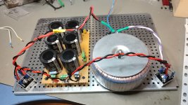
for my muse edition the progress is good. new CRC with 3x33mF each (i forgot the bleeder resistor). to be honest this was the last time i built a CRC with just a easy pcb.
i will use a CL60 NTC on the primary of the transformer (2x24V 300VA) because of the huge caps.
have fun
chris
i will use a CL60 NTC on the primary of the transformer (2x24V 300VA) because of the huge caps.
have fun
chris
Attachments
Good Morning, there is a little Thread about NTC's https://www.diy-hifi-forum.eu/forum...scher-Endstufen-und-mehr-selber-bauen!/page10 At Post 188. That is a nice Idea and more safety.
About the FX8...
My testing heatsink has arrived. Perhaps i can make a little test in the next days. For testing i will use a transformator 25 Volt/250 VA with 20.000 µf per Rail. The finally case i ordered by Aliexpress. I'm waiting for delivery. I finally decided to use the original pcb's FX8 Bimo Mod.
In the last built i will use a Connex SMPS +-36 Volt 300 or 500 Watt. All my Amps are running with Connex SMPS. No problems with a SNT...
I think i will set the bias for my FX8 to 100-150 ma. That must be enough in my case.
On the Picture you can take an look at my goldmund clone. Thats the last amp i built. 100 ma bias and it sounds very good....
Have a nice day
Peter
Attachments
Hi Kleinhorn
nice amp - your goldmund clone.
NTC:
this thread is talking about (post 188) varistor (for high voltage peaks to safe the pcb) and that is a different component then a NTC (CL60).
i build enough First Watt amps to know that a CL60 or similar help the power on current at the primary of the transformer to load the huge caps after the rectifier safly - so without blowing the primary fuse or damaged the transformer.
so what is your point? sorry i dont get it.
FX8:
what happend with your own PCB?
have fun
chris
- Home
- Amplifiers
- Solid State
- APEX FX8 bimo mod
