i wrote in post #82...
"next will be to enjoy then test around with more power-->"
lets talk about power:
Power is maybe not always useful because of HEAT! be aware that you have to check the SOA (saftey operation area) of the transistors. always. Class A or Class AB never mind! and use bigger heat sinks, and housing.
more power demand a "better" = stronger PSU.
1- Trafo more VA..to get more power for charging the Caps
- or more Voltage more power into 8R...i use 24V secondary give after rectifier about 31,5V per rail with my "class A " bias setup (750mA) idle.
please use exactly the fuse which is in the datasheet for secondary and primary windings. Trafos are expensive.
as ZEN Mod says--- if you need more power use not more force use a bigger hammer...means buy a bigger trafo, build a stronger PSU.
2 caps..better power is more current demand and together with the Trafo you will get more power, but please do not forget that your rectifier must handle this current. means that a huge current demand must be loaded over the rectifier to the caps and then to the amp.
3 rectifier..I use the standard rectifier...cheap and does the jop. B700C35A. Here is an update possible without pay for a new trafo.
you can use a active rectifier with the LT4320 and fast MOSFETS.
here is the thread:
here:
this active rectifier is not cheap because this LT4320 is about 10 euros and then you need fast switching MOSFETS...so about 18 euro. but you get about 2Volts extra per rail...so more power and this rectifier stay cool.
bye
chris
Hello guys
after some compare test with other amps i have re adjust the bias back to about 400mA quiescent current.Why? i wrote that i like the bigger bias and got a Semi Class A but final i found that a lot of "attacks" are too smeared.
so i have to say, you loose more with bigger bias. nevertheless the Lateral MOSFET have a positive tempco - that means more heat makes them less conductive- that's triggers me to go back to the recommended current of about 400mA.
the good thing is that this amp can be setup like you want! 😉
chris

Hi to all
I did a small update with the VAS Transistors Q5, Q6:
KSA1381 E pnp have hfe about 150
KSC3503 DS npn have about 90
yes this series fits not together in hfe class (my fault)
I use pin headers at this place so i am able to change easy the VAS stage:
i use my TTA04B Q and the TTC004B_Q with better match (220, 210)
after 2 days checking and changing the VAS transistors i am happy with the sound and no the Toshiba's are not "louder".
sound is for my taste better. less "white noise", better bass, deeper sound stage.
i do not know what makes it better because according to the datasheet the KSC/KSA have lower Cob and better transit frequency of 150MHz. Toshibas are with 17pF Cob and 100MHZ. so the closer matching do the trick?
if you need matched pairs aof KSA/KSC ask this guy:
matched
have a nice day
chris
Hi Chris,
You ask for a new Layout in the FH9 thread...
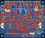
The Layout of the FX8 is bigger than the layout of the FH9 because of the two fuseholders. Kicad symbols/footprints are bigger in some case. Don't know if it is possible to get the pcb smaller. Perhaps i can make a smaller pcb putting the drivers to the outside. I will see what is possible...🙂
Peter
You ask for a new Layout in the FH9 thread...
The Layout of the FX8 is bigger than the layout of the FH9 because of the two fuseholders. Kicad symbols/footprints are bigger in some case. Don't know if it is possible to get the pcb smaller. Perhaps i can make a smaller pcb putting the drivers to the outside. I will see what is possible...🙂
Peter
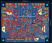
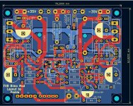
The original pcb had a size of 100 x 83mm. I made a new layout, little bit smaller. But not finished yet. I have to look after the coil, if there is enough space to the fuseholder.
I will have a look if i can provide some crossing. Not many crossings on the pcb...😉
Here it is...
I will have a look if i can provide some crossing. Not many crossings on the pcb...😉
Here it is...
Attachments
I ran this amp at 1A bias current in class A once.
https://www.diyaudio.com/community/threads/100w-ultimate-fidelity-amplifier.164093/post-5203929
Being a latFET amp, it is inherently thermally stable.

https://www.diyaudio.com/community/threads/100w-ultimate-fidelity-amplifier.164093/post-5203929
Being a latFET amp, it is inherently thermally stable.
You are the GREATEST ! Peter !
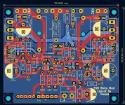
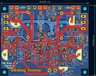
mybe the transistors Q1 + Q3...differential input pair closer together because of thermal coupled
mybe the transistors Q1 + Q3...differential input pair closer together because of thermal coupled
Peter- that is perfect for me/us.
wait a bit...maybe others have some ideas - then gerber file
thank you !!!
wait a bit...maybe others have some ideas - then gerber file
thank you !!!
Hi...
You can give me sign, if no more ideas.
The crossings around the input transistors i do not like..i have look...
Peter
You can give me sign, if no more ideas.
The crossings around the input transistors i do not like..i have look...
Peter
hmmm... i am not a KICAD expert but for me it looks okay.
the thermal coupling of this pair should be mandatory.
also XRK did use a white tube for better coupling. post 109
the thermal coupling of this pair should be mandatory.
also XRK did use a white tube for better coupling. post 109
- Home
- Amplifiers
- Solid State
- APEX FX8 bimo mod