The 1Meg resistors are only for "turning on" schematic. Since it is absolutely symmetric (at least on a paper) in their absence it will rely only on the differences between p-n-p and n-p-n transistors etc. for the initial starting process. Once transistors start conducting, the currents via 1Meg resistors become neglectable.
P.S. Адаш, i think I explained it well, did I? 🙂🙂🙂🙂
P.S. Адаш, i think I explained it well, did I? 🙂🙂🙂🙂
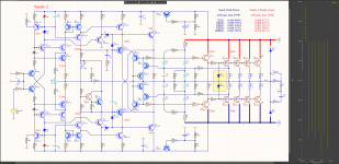
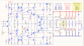
Current D1, D2 is 2mA and comes
for D1 T5 (T4-T2-T5)
for D2 T6 (T3-T1-T6)
R7-R10 are only for the initial startup.
DC in output is only 1mV
However simulator transistors are the same.
for D1 T5 (T4-T2-T5)
for D2 T6 (T3-T1-T6)
R7-R10 are only for the initial startup.
DC in output is only 1mV
However simulator transistors are the same.
Attachments


Last edited:
Upload a photo of your schedule to see where your error.
It is not MY error. It is YOUR error in YOUR schematic.
It is described in the text in reference to your last schematic with resistor number reference in end of the line.
With 1 MOhms resistor, the zener is not polarized and both current sources do not have current to start up.
Last edited:
So much force where there is moderate talent. So much talent where there is moderate force. Go on with the PCB. Some details about components are over optimistic or pesimistic on simulation. Validate in bench.
So much talent where there is moderate force.
He only need to study how to polarize a Zener Diode correctly. The arrangement he did is very good to improve PSRR.
If he assembly only this little circuit in the bench to light up a LED all will be clear to him.
Regards
Yes but my circuit behaves correctly in the simulator, but yours is not working correctly.
Upload a photo of your schedule to be able to discuss things correctly.
Upload a photo of your schedule to be able to discuss things correctly.
This schematic already has power-based limitation circuitry which follows the SOA curve. It is based on the idea described in the Michael Kiwanuka's paper "The Safe Operating Area (SOA) Protection of Linear Audio Power Amplifiers". It's another question if you're thinking about some latching protection.how abput to add short circuitt protect ?

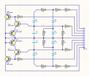
Concerning the SOA protection circuit some time ago I've made a small board in order to use it on various amplifier boards and to be able to (almost) easily change the limits.
Till now I haven't an idea for sharing it since the transistors in SC-70-6 package are not a spoon for any mouth 🙂 but since Sandy opened the theme, who knows ...


Till now I haven't an idea for sharing it since the transistors in SC-70-6 package are not a spoon for any mouth 🙂 but since Sandy opened the theme, who knows ...
Last edited:
OP, there's no need for aggression, thus towards groups of people which aren't mentioned as a debate subject of this topic.
Seriously, this thread is a great example how to lose interest in pursuing reading further. Do as you will, but I would take Elvee and Eva's words with care. So much for talent. 😕
Seriously, this thread is a great example how to lose interest in pursuing reading further. Do as you will, but I would take Elvee and Eva's words with care. So much for talent. 😕
As SMD will be only SMD.
Protect 3D.pdf is a 3D opens only with Adobe
Protect (on 30.12.2019 00-00-45) Altium Designer project
Protect 3D.pdf is a 3D opens only with Adobe
Protect (on 30.12.2019 00-00-45) Altium Designer project
Attachments

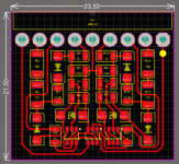
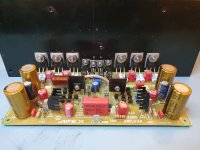
Ha, Адаш - of course I know you'll make it better 🙂🙂 but I deliberately used some through-hole components. After all we have a quiet high voltages here and I'd prefer to be on a safe side when output signal makes an excursion from maximum to minimum. The dissipated power also must not be excluded from account.
Therefore, R2, R3, R13, R14 are two and 1206 (0.25W)
1206 150V max becomes and the power amplifier with +/- 150V
1206 150V max becomes and the power amplifier with +/- 150V
Last edited:
my 5 cent: i am maybe the only one that is going to stand before APEX as a MAN,that has shared almost infinity of combinations of VAS OPS and many other ..S combinations to this and many other forums all around the world. there is almost too much of his,before posting schematics and details to this forum (among all others) designes that were prooved working not only good to ear,but also on a bench,connected to RC load and measured working (mild said) correctly under various difficult conditions inclooding real life conditions,harsh by the way. i have made more than a dozen of them tested before posting-by APEX on internet. i have also draw at least a dozen of PCBs by his designes-and they all worked stabile as my humble equipment could show(sinus square test signal at input,150Hz - 150kHz range),with reasonable results regarding used components and expectations.
is there any place for improvements? naturally yes.
has anyone of you here seen any amplifier made from first round working perfectly-with no any possible improvements? maybe,but in a say first month of an idea... later,there came improovements,by author or others.
i have seen many amplifiers growing from basic idea to something compleetly new,so new it needed to have a new topic. so-there is no idea with no improvements. more minds think more widely,don t they?
back to APEX- this man has put to paper more designes that worked "as it is",than i posted posts at this forum. did he made some mistakes-yes he did. could all of them been better-yes they could. but 95% of them worked from it s first attempt! take a look at threads of ostripper,from Dadod...and all others designers here: they have all something on their mind and prooved that basic idea works. later,they have made it several times more and same amount more better working! they based on their ideas and made them better and better by the way.
APEX does it in other way: he presents us his basic ideas in schematics,he lets us to try them and does not forbid us to make them better,stronger... many of his PA amps with say 250W of output power were made TEF and double or tripple more powerful.
i am construction worker(dry wall and celings worker) and assemblng amplifiers and preamplifiers is my hobby. APEX made me seeing parts of an amplifier to it s parts,many different of them-working as one.
please,do not put negative assumptions to a man,because this man has put more ideas and combinations (IPS OPS ...) to this forum than (my opinion) any other man did on any forum on the internet.
that deserves,i would asy,at least a bit of respect and less words as "poorly decizions" and "poor designes".
proove your selves right through some working and tested designes first,please. and than try to reach as many combinatios as he did untill this moment... if it is no trouble to do it so.
and one more sentence to say-when A40 from this topic proves to be wrking better.i have no trouble to do it for my self-if the author would say i can make one for my self.
APEX is not the only one desgner by wich i made my devices,there are others too. but they have some other names and countries than...so it makes them right. or it appears so.
Last edited:

I totally agree with you.
My A40 starts singing from the first attempt itself 🙂 No modifications or adjustments done other than the ones mentioned by Mr.Mile. I always feel that the Apex designs are more diy friendly for beginners and mid-level hobbyist. Also Apex use most commonly available parts in his designs.
Now I am in the middle of Apex P30 pre 🙂
Thank you
Sha
my 5 cent: i am maybe the only one that is going to stand before APEX as a MAN,that has shared almost infinity of combinations of VAS OPS and many other ..S combinations to this and many other forums all around the world. there is almost too much of his,before posting schematics and details to this forum (among all others) designes that were prooved working not only good to ear,but also on a bench,connected to RC load and measured working (mild said) correctly under various difficult conditions inclooding real life conditions,harsh by the way. i have made more than a dozen of them tested before posting-by APEX on internet. i have also draw at least a dozen of PCBs by his designes-and they all worked stabile as my humble equipment could show(sinus square test signal at input,150Hz - 150kHz range),with reasonable results regarding used components and expectations.
is there any place for improvements? naturally yes.
has anyone of you here seen any amplifier made from first round working perfectly-with no any possible improvements? maybe,but in a say first month of an idea... later,there came improovements,by author or others.
i have seen many amplifiers growing from basic idea to something compleetly new,so new it needed to have a new topic. so-there is no idea with no improvements. more minds think more widely,don t they?
back to APEX- this man has put to paper more designes that worked "as it is",than i posted posts at this forum. did he made some mistakes-yes he did. could all of them been better-yes they could. but 95% of them worked from it s first attempt! take a look at threads of ostripper,from Dadod...and all others designers here: they have all something on their mind and prooved that basic idea works. later,they have made it several times more and same amount more better working! they based on their ideas and made them better and better by the way.
APEX does it in other way: he presents us his basic ideas in schematics,he lets us to try them and does not forbid us to make them better,stronger... many of his PA amps with say 250W of output power were made TEF and double or tripple more powerful.
i am construction worker(dry wall and celings worker) and assemblng amplifiers and preamplifiers is my hobby. APEX made me seeing parts of an amplifier to it s parts,many different of them-working as one.
please,do not put negative assumptions to a man,because this man has put more ideas and combinations (IPS OPS ...) to this forum than (my opinion) any other man did on any forum on the internet.
that deserves,i would asy,at least a bit of respect and less words as "poorly decizions" and "poor designes".
proove your selves right through some working and tested designes first,please. and than try to reach as many combinatios as he did untill this moment... if it is no trouble to do it so.
and one more sentence to say-when A40 from this topic proves to be wrking better.i have no trouble to do it for my self-if the author would say i can make one for my self.
APEX is not the only one desgner by wich i made my devices,there are others too. but they have some other names and countries than...so it makes them right. or it appears so.
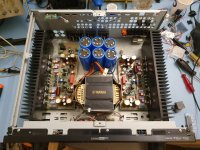
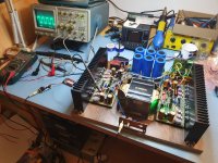
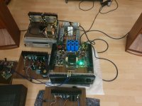
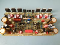
My Apex soud very well too, but after replacing the MJE transistors with proper ones.
Also I replaced 10оhm resistors in PSU rails with Capacit multiplier, due to the bad PSRR of this kind amplifiers (CFA).
Although i am happy with the amplifier, i consider to try the modified version in this topic.
I must say that it is very unprofessional to asseble pcb for the original Apex A40 without annotation in the schematic.
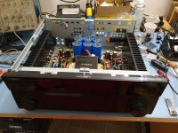
Here are some pics of my test wood board...
Also I replaced 10оhm resistors in PSU rails with Capacit multiplier, due to the bad PSRR of this kind amplifiers (CFA).
Although i am happy with the amplifier, i consider to try the modified version in this topic.
I must say that it is very unprofessional to asseble pcb for the original Apex A40 without annotation in the schematic.
Here are some pics of my test wood board...
Attachments
-
 72276115_420035102281407_5299328012141985792_n.jpg176.5 KB · Views: 536
 -
 78166194_462945871005781_504090338617458688_n.jpg172.2 KB · Views: 492
 -
 76713971_2545000662249005_5773955626728161280_n.jpg124.5 KB · Views: 489
 -
 75204565_997851550563595_4892577811593691136_n.jpg123.7 KB · Views: 511
 -
 20191027_134956.jpg120.7 KB · Views: 578
 -
 20191027_135002.jpg885.7 KB · Views: 577
 -
 74703512_2559616977644853_4542358799524036608_n.jpg139.9 KB · Views: 488
Sandy, did you actually build your amp?
Or do you have any updates on it?
Do you consider your latest published version as final, and worth to actually build?
Or do you have any updates on it?
Do you consider your latest published version as final, and worth to actually build?
- Home
- Amplifiers
- Solid State
- Apex A40 fundamental improvement. (Sandy)