Don't fantasize when you don't understand. Not true.
They are used as ordinary diodes.
Zeners are chosen because they have a larger drop and during normal operation the current through them is uA.
And in short mode do not limit the current naturally.
They are used as ordinary diodes.
Zeners are chosen because they have a larger drop and during normal operation the current through them is uA.
And in short mode do not limit the current naturally.
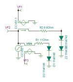
A conventional 1-4u film capacitor is an equivalent replacementWhat is the role of D7/D8 ?
Don't fantasize when you don't understand. Not true.
They are used as ordinary diodes.
Zeners are chosen because they have a larger drop and during normal operation the current through them is uA.
And in short mode do not limit the current naturally.
As far as I know, zeners were placed in the cathodes of cascades with a common anode.
I see, R1/R2, 30k/1k balances the negative 3k/1k. CFA designers not to mention don't know this technique.With CFA, ground loop breaker causes inter channel crosstalk and it will with your circuit also.
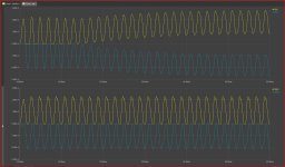
Comparing diode of Zener and 1n4148
With 2×3.3 ohms this is current of the diodes in red 1n4148.

and with 2×5.5 ohms for 1n4148

Are these diodes following in temperature the output transistors?
With 2×3.3 ohms this is current of the diodes in red 1n4148.
and with 2×5.5 ohms for 1n4148
Are these diodes following in temperature the output transistors?
Attachments
Last edited:
Watch the diagram from # 94I see, R1/R2, 30k/1k balances the negative 3k/1k. CFA designers not to mention don't know this technique.
R2/R1 30k/1k
(R25+R28+R30)/R4 (1k+1k+1k)/100 3k/100
Yes, yes I did remark my error of 1k instead of 100 ohms. I wonder if the 30k should be adjustable.
You probably don't know, but when a pulse current flows through the capacitor in only one direction, it is charged.🙂I made a model with zeners . There is no difference with capacitors. I stand by my opinion
Attachments
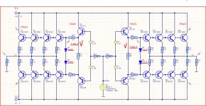
Comparing diode of Zener and 1n4148
With 2×3.3 ohms this is current of the diodes in red 1n4148.
View attachment 901668
and with 2×5.5 ohms for 1n4148
View attachment 901669
Are these diodes following in temperature the output transistors?
Attachments
I agree that you can adjust 120ua in diodes, but when the outputs go hot, the 120ua evaporates as the voltage across the diodes decreases. If you add a resistor along the two 1n4001, can't you also get 120ua?
Try to think again about what will happen when the final transistors heat up.
They are on the heatsink and the diodes on the board.
By heating the radiator, the thermal compensation circuit will reduce the base / emitter voltage and therefore the voltage across the diodes, and the current through the diodes will decrease even more.
They are on the heatsink and the diodes on the board.
By heating the radiator, the thermal compensation circuit will reduce the base / emitter voltage and therefore the voltage across the diodes, and the current through the diodes will decrease even more.
Last edited:
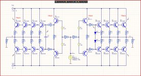
The images were taken from vegalab, but they are not very good in terms of distortion. In the Minek branch, the parameters of the proposed amplifiers are better with fewer elements and a larger loop gain.
current feedback power amplifier
Nice to see the early version of my power amplifier 🙂
Sajti
https://www.diyaudio.com/forums/att...rajz-png-070ba69a5babab240a5cd2593861d0c3-png. - Where can i read about it

Hi,
it has only very short topik in english. The whole story behind available only in hungarian language. The final version use bit different semiconductors.
Sajti
it has only very short topik in english. The whole story behind available only in hungarian language. The final version use bit different semiconductors.
Sajti
I was not banned in Google translate, please give me a link to Hungarian, I will try to read it...
- Home
- Amplifiers
- Solid State
- Apex A40 fundamental improvement. (Sandy)