Heres the link to download Music Recorded With Transfer Level -60 dB
Try playjng this recording if you haven't already. Ill give the circuit a go this weekend.
Try playjng this recording if you haven't already. Ill give the circuit a go this weekend.
Got it.. when its turned all the way up, should there be silence behind the jazz track?.. because it sounds suspiciously like the fuzz that I think I'm hearing..
Normal listening is silent, but as its turned up the noise floor doesn't sound like analog noise.. its more like static noise.
If you can, try it with carbon film resistors as well…
I'm quite hopeful that metal films will give all the benefit without this fuzz - which isn't even noticable so much but you can still pick it up. Its odd. Something closed mic piano well recorded like keith Jarret and its silent until he shuffles on the chair, but during more complex stuff you can sort of feel it more than hear it..
Last edited:
The way I understand it there are advantages to simultaneous data mode at 44.1 too. I haven't looked at simultaneous data mode timing diagram in detail for a while, I did think it was shown to have advantages like allowing additional 'silence' on the input signals during conversion time.
It is Ian's half speed mode clocking that enables 352 and 384k in TDA1541 though it is still clocked above spec at those speeds and I'd love to check (measure) distortion while the chip is being 'over clocked'.
The third thing that the i2s to PCM board gives is a clean reclocked set of inverse data outputs so you can more easily set the DACs for differential output.
How audible all of those differences are is hard to know but a lot of multibit fans nagged Ian to do that board up and they all seemed like robust reasons at the time.
Cheers,
Chris
Hi Chris and ryan, thanks for the info, I dont fully understand what the benefits might be of differnt clock speeds or differential, but I think youve helped me make up my mind so thanks.
Im going to go for a simple fifo board feeding a tda1541. I will buy the add on clock for the crystal as power supply for clocks have made improvements for me in the past.
the good thing about Ians kit is you can try new things in the future as you like.
Any ideas on usb inputs to use?
Grab a RaspPi, use Volume or the like and the Pacific header direct into the fifo, it's better than USB and cheaper too......
Networked from a nap drive, works nice and clean!
Chuz,
Drew.
Networked from a nap drive, works nice and clean!
Chuz,
Drew.
Grab a RaspPi, use Volume or the like and the Pacific header direct into the fifo, it's better than USB and cheaper too......
Networked from a nap drive, works nice and clean!
Chuz,
Drew.
Hi Chuz, ive looked into raspberry pi, but i think i prefer foobar2000 or maybe switch to jriver. MPD seems to be the only player for pi and it looks a bit basic. You know of any other players for pi?
There are add ins etc for MPD, but really, look at volume or rune, interface via phone, it works and sounds pretty freaking good, ask Super surfer his thoughts compared to wave is and a pc etc......
Who is Chuz?
Chuz(cheers),
Drew.
Who is Chuz?
Chuz(cheers),
Drew.
Sorry Drew, I missed your name. Thanks for the tip. There are almost too many options these days.
Hi Drew,
Do you think it's possible to feed with a RasberryPi base the coreboard with I2S and have a clone of squeeze box server in it with the embeded RJ 45 ?
Did you try it or have some links for us ?
The big interrest of the core board here is to be fed by different options (as well Pedja did also with the 2014 rev of the AYA 2 & its uf.l. connectors).
The day trhe coreboard will be ready, I believe the RasberryPi to be a good option to the more classic USB... some of us have data librairy with local network and not a factory with fans near their preamp and DAC 😀
Ryan,
After your first tests, do you need some good suppliers contacts to print the board at a good price ? Can we help you to ask to some others fellows who already make projects at DIYAUDIO. I think some of them have a good geographical position and/or private professional experience of this material part of such a project...
Any date for the closing of the first version of the core board ? Maybe a last look for people like Marce if he want ?
What are your opinion here ?
Set3up, always here with us ? Did you suceess to do something at your own side ?
Any inputs or ideas for the core board ?
regards,
Eldam
Any inputs or ideas for the core board ?
regards,
Eldam
Last edited:
Got it.. when its turned all the way up, should there be silence behind the jazz track?.. because it sounds suspiciously like the fuzz that I think I'm hearing..
Normal listening is silent, but as its turned up the noise floor doesn't sound like analog noise.. its more like static noise.
If you can, try it with carbon film resistors as well…
I'm quite hopeful that metal films will give all the benefit without this fuzz - which isn't even noticable so much but you can still pick it up. Its odd. Something closed mic piano well recorded like keith Jarret and its silent until he shuffles on the chair, but during more complex stuff you can sort of feel it more than hear it..
You will hear the noise floor of your system, but the music should not be distorted, just quiet. Do you hear the same noise without the resistors?
Ill get some carbon film from jaycar today and test it out.
Ryan,
After your first tests, do you need some good suppliers contacts to print the board at a good price ? Can we help you to ask to some others fellows who already make projects at DIYAUDIO. I think some of them have a good geographical position and/or private professional experience of this material part of such a project...
Any date for the closing of the first version of the core board ? Maybe a last look for people like Marce if he want ?
What are your opinion here ?
Hi Eldam,
The test boards should arrive in the next week. I've found a PCB fab shop local to me. They can provide a 1.2mm board (important for impedance matching) and ENIG - Electroless nickle/immersion gold finish. But if anyone knows of any other good and cheap PCB manufacturers in all ears.🙂
Hi Ryan,
So I still would try it, but it might be easier to go to Jaycar and get 2x 6k8 resistors, take Johns word for it and not think back about it.
Shane
I did just this using two carbon film 6k8. Function verified with -60dB recording - all ok. Had a listen for about an hour and my toe tapping didn't stop. But as you all know listening enjoyment is very dependent on mood so ill have to have another listen later on tonight with a few beers.
I did just this using two carbon film 6k8. Function verified with -60dB recording - all ok. Had a listen for about an hour and my toe tapping didn't stop. But as you all know listening enjoyment is very dependent on mood so ill have to have another listen later on tonight with a few beers.
Thanks Ryan,
I was playing back in the main system just before and not noticing that which bugged me through the headphones. It wasn't like that without the resistors, no. My best guess is that I was objecting to when vocalist opens his mouth from pursed lips and it makes a slight pop sound but I really don't know, it all gets pie in the sky after a bit.
The 39.wav kind of threw me, I wasn't understanding how to interpret it, cranked it right up and hey heres the noise floor. Its not a pink/white noise sound, its a static sort of thing, guess the head amp is quieter. And I tell ya, don't let it roll through to the next song on the play list - learned that the quick way.
Based on that I'd say (guess) its lowered noise somehow and picking up stuff not noticed before.. still, none of that (which I really don't like, its annoying) comes through with speakers in the main system… so its a win - win.
Shane
Last edited:
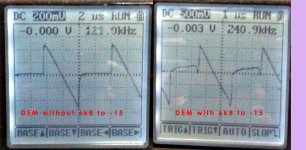
DEM with and without 6k8 to -15V
I've taken a look at what's going on with the DEM with and without the 6k8 resistors to -15V.
They were taken from different chips running at slightly different speeds but I think this shouldn't affect the shape of the waveform.
Take a look and see what you think.
Looks to me like there is less RF energy in the waveform with the resistors. Its almost as if the waveform has less force imposed on it. But then again i think i may have had a few too many beers to be the judge... and i know that the images aren't the best but thought i might share for the sake of a common interest. 😕
Attachments
Last edited:
I've taken a look at what's going on with the DEM with and without the 6k8 resistors to -15V.
They were taken from different chips running at slightly different speeds but I think this shouldn't affect the shape of the waveform.
Take a look and see what you think.
Looks to me like there is less RF energy in the waveform with the resistors. Its almost as if the waveform has less force imposed on it. But then again i think i may have had a few too many beers to be the judge... and i know that the images aren't the best but thought i might share for the sake of a common interest. 😕
I'm happy to know that there is a difference and that its not just all inside my head (for once).
What does that deviation from horizontal between the two waveforms represent?.
If -15V is the analog section supply voltage of the chip.. .. ..
Dunno but interesting, maybe John could comment?. Would you post over in his thread, or if not, I would..
edit: I've just noticed one is more than twice the amplitude of the other.. and twice the frequency.. any chance you could take two on the same scale and at the same frequency?.. I'd be keen to see what happens to that deviation which looks kinda worrisome.
Last edited:
I'm happy to know that there is a difference and that its not just all inside my head (for once).
What does that deviation from horizontal between the two waveforms represent?.
If -15V is the analog section supply voltage of the chip.. .. ..
Dunno but interesting, maybe John could comment?. Would you post over in his thread, or if not, I would..
edit: I've just noticed one is more than twice the amplitude of the other.. and twice the frequency.. any chance you could take two on the same scale and at the same frequency?.. I'd be keen to see what happens to that deviation which looks kinda worrisome.
Yeah im really not sure what it all means. If i get time today i'll remeasure to try and get more accurate and meaningful representation of what is going on. 😀 ... but the kids are running around like crazy at the moment...

Yeah im really not sure what it all means. If i get time today i'll remeasure to try and get more accurate and meaningful representation of what is going on. 😀 ... but the kids are running around like crazy at the moment...
I just saw your post in Johns thread.. nice one.
You need to teach the kids to solder SMD then open the shop for business ;p
I just saw your post in Johns thread.. nice one.
You need to teach the kids to solder SMD then open the shop for business ;p
lol haha. not a bad idea, might have a good production line going in a few years.. let the 1541 live on.
lol haha. not a bad idea, might have a good production line going in a few years.. let the 1541 live on.
yup, its not slave labour if you feed them.
could you use the same sampling rate for the screen shots and then try again with metal film?… yeah I know.. but you're the one with the oscilloscope 😀
edit: and the same chip !!
Last edited:
- Status
- Not open for further replies.
- Home
- Source & Line
- Digital Line Level
- Any good TDA1541A DAC kit?