HelloNo, but you can get a cleaner B+, less rectifier and transformer noise.
Psrr is all about how the circuit manages a not so good power supply.
The Lundahl 15H is a nice number for choke input but you will need a different transformer!!
Greetings Eduard

Find it hard to read...But I just found a transformer in my parts box with same dimensions but with 350V.You can see in the first graph how much ac you need
Come to think of it with a hybrid graetz bridge I even have 400/500/600V. With the transformer mounted now. 😀
Make C1=60uF and
Bob's your uncle!
Make c2=90uF
And Fanny is your aunt!
And so on and so forth. I can just keep adding capacitance it seems and no ringing.
Last edited:
Hello Bas,
Dcr of one half of the high voltage winding is 400 ohm?
You should put a bleeder resistor across the first cap to make it work at choke input all the time.
If dc at first cap is 350 volt and choke is 15 H then there should be 350/15= 23,3 so let us say 25 mA running through that resistor. Take care of the heat and the voltage rating!!
You did not put a delay in your simulation on purpose? It will take some time to charge the caps.
I did not take my reading glasses outside and my device has a small screen but the simulations do look good?
The horizontal lines are the dc voltages. On the left side you see the ac input and on bottom you see the current. Of course if you use psud you can also get the results. If i remember well you should use the voltage without a load so a bit higher than the ones indicated at the transformer.
The first cap, even after the choke should not be that big. Usually making the last cap bigger works better.
Greetings,Eduard
No that is still a remnant of my fetish. (150R in each leg) Still not sure if it should be total resistance or just one half of the high voltage winding.Dcr of one half of the high voltage winding is 400 ohm?
Check.You should put a bleeder resistor across the first cap to make it work at choke input all the time.
If dc at first cap is 350 volt and choke is 15 H then there should be 350/15= 23,3 so let us say 25 mA running through that resistor. Take care of the heat and the voltage rating!!
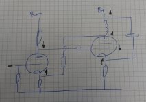
Just did a sketch of the amp with ultrapath cap to see how the phase of the noise behaves, it does not look good - but to all, feel free to comment.I use this sort of feedback without hummmm, but it is in a PP amplifier where it may well cancel out.
I was thinking if ultrapath connection of the cathode bypass cap would be an option to improve PSRR? I will have a better look at it later...
https://www.tubecad.com/2008/08/blog0147.htm
Say the ripple at the B+ goes up (shown by the arrow up). This ripple will be present at the plate of the tube (impedance of the transformer is much higher than the plate impedance). The ripple will be passed (attenuated) to the cathode of the driver tube. Given there is no ripple at the grid of the driver tube, the ripple at the plate of the driver tube will be inverted, and passed to the grid of the output tube. The cathode of the output tube gets the ripple from B, so the cathode and grid of the output tube have ripple in opposing phases, which then gets amplified (and not cancelled, what I hoped for).
Does it make sense?
Indeed, lots of filtering will help, personally I have no problem with that approach 🙂
Attachments
Thanks Erik for helping to try and find a solution. The dutch word is quite descriptive. Bedankt voor het meedenken.
Mmm I see my transformer starts at 250vac. So no 400 with hybrid bridge.
So the other transformer it will be.
So the other transformer it will be.
Hello Bas
Sometimes you see some ringing during switching on but i am not sure if that is a serious problem.
I think once things are settled the choke should correct disturbances if i am right. So see in the first graphic that the dc voltage not changes a lot when current changes.
Sometimes changing the value of the first cap can make the startup more gradually or add a resistor in series with the choke or with the secondary winding.
Because this is a power amp i don't think it is necessary to try reducing the ripple to an absolute minimum. Sometimes better quality caps with lower value will sound better than low quality cap with bigger value.
At least you have a very good choke.
Of course putting the last power supply cap very close to the output transformer is a good idea.
Greetings Eduard
I juggle the inductor and cap values until I get a decent step change of the output voltage. A little overshoot usually equates to a faster responding supply.

Hello,
This is not even close to the specs Bas is looking for.
The Lundahl choke is 15 H and 64 ohm.
Going lower in Henry will be a bad idea because you will need to send more current through the load resistor. You can change behaviour by adding a resistor in series with the Lundahl, or adding a pair on series with the secondaries ( don't know which one would be the best) or changing the value of the first cap.
Often you will the see the voltage rise on the first cap a bit irregular and the rise on the second cap going smoothly.
I am not sure if this irregularities are that important with a choke input because the choke will keep the current flow at the steady level while with a cap input there will a continuous switching,
It could be that you cannot obtain your desired dc voltage and this could possibly lead to a bit lower power output from your amp. BUT i am sure a 4 watt amp with choke input will sound more powerful than a 6 watt with a cap input supply.
Of course you could try a temporary modification to just check if i am telling the truth. Just put another high voltage transformer next to your chassis. If you hear an improvement it will only get better once you have everything connected with shorter wires.
Greetings Eduard
It's just to show how he does it.This is not even close to the specs Bas is looking for.
Hello Bas,
Once you are sure you have a transformer which has enough ac voltage ( current rating can be lower than with a cap input because there will be no more charging pulses, so current through tubes, plus bleeder plus 20 % is enough) you should give it a try. Don't need to optimise it right from the start. The only thing really important right from the start is to take care of the minimum current, 25 mA it must be there all the time.
Greetings Eduard.
Beautiful dead bug construction! Love that!
Hello
Ask you can see the bleeder resistor will heat up considerably. I use Lundahls with higher H but i will still use at least 3 times the dissipated power rating. I prefer the resistors that you can mount in the air. The aluminium ones you can mount onto the chassis need a big chunk of aluminium to be properly cooled down. Just create some space around the resistors.
Greetings Eduard
Hello Bas,
This link contains some nice info on why choke input is the way to go.
https://ken-gilbert.com/choke-input-power-supplies-part-1-henry-pasternack/comment-page-1#comments
Greetings Eduard
This link contains some nice info on why choke input is the way to go.
https://ken-gilbert.com/choke-input-power-supplies-part-1-henry-pasternack/comment-page-1#comments
Greetings Eduard
- Home
- Amplifiers
- Tubes / Valves
- Another SE EL84. Following this schematic. Grid stoppers yay or nay?