Flavio88, is the voltage for your driver stage only +10volts? Or is it 10volts more than the output stage, which should be the case?
😀 😀 😀 is the second case... positive rail plus 10v
but i have tryed also with normal + rail(without the 10 v increase)
but not worked.
is possible that the problem is the other types of drivers i used?
but i have tryed also with normal + rail(without the 10 v increase)
but not worked.
is possible that the problem is the other types of drivers i used?
And I have found a problem with mine....sorry but I gotta fix mine first.
Anyone contemplating using my layout should wait until I fix it.
Cheers
Anyone contemplating using my layout should wait until I fix it.
Cheers
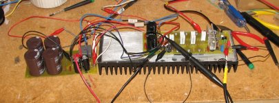
AndrewT said:Hi Quasi,
that must be some fix if it took all those wires to cure a board error! 😱 😀
Ha !
It does look a mess, but the mess is 3 x AC into the power supply, 3 x DC feeds plus ground into the amp. Two voltmeters are connected plus a CRO and an input signal lead. The 2 x 5 watt resistors are there for protection (JIC). The board fault can be spotted by the now green legged transistors that had to be twisted a bit. 😱 oh well....
Cheers
Q
Flavio88 said:i'm getting crazy..... please someone help me!!!!
Can you post some voltages that you have measured?
Cheers
Q
Flavio88 said:i'm getting crazy..... please someone help me!!!!
Have you already measured r16/19 ?
Also interesting would be R4/9. Have you checked if orientation of bd139 is correct ? You should rotate the elyts in feedback and input, they have wrong polarity. Also skip the filter caps in frontend, you connected them to signal-gnd. Why did you use old schematic ?
Mike
i have tryed to adjust VR1 but the voltage accross R4 and R9 changes insignificantly...
adjusting the bias the problem remains...
adjusting the bias the problem remains...
however i 've decided to start project with another schematic... too many problems to fix...🙁 
quasi, the problems of the last board you have posted are layout related only or it's schematic problem?
what schematic i should use for a working amp????
can i use the schematic attacched without problems???
quasi, the problems of the last board you have posted are layout related only or it's schematic problem?
what schematic i should use for a working amp????
can i use the schematic attacched without problems???
Attachments
The problem with mine had more to do with the PCB layout (I had the first stage transistor pinouts incorrect).
The second schematic is one further developed from the one you used and my advice is not to use it yet. This schematic is the one that I have on my bench now and it needs some more work before it can be considered robust.
If you are in a hurry then build my other design. Many of these have been built by very happy constructors and it is proving to be a very stable amp.
This link will take you to the near the middle of the thread.
http://www.diyaudio.com/forums/showthread.php?postid=945573#post945573.
Cheers
Q
Observation and discussion sought
Ok so here's the thing. The amp works well but the negative rail clips first. This I imagine is because T7 runs out of drive as the output swing close to negative rail.
Any thoughts?
Do I go back to the cascode arrangement. I know that arrangement allows the amp to swing rail to rail.
Cheers
Quasi
Attached is the latest schematic.
Attachments
Yes, i didn't thought at that problem, T7 enters reverse bias, the output being more negative than gate drive... 🙁
A solution might be connecting r21 to the top of r20. This should be possible to try on actual pcb.
Yes, the problem wouldnt exist with t7's base connected to gnd.
Mike
A solution might be connecting r21 to the top of r20. This should be possible to try on actual pcb.
Yes, the problem wouldnt exist with t7's base connected to gnd.
Mike
Why not connect the top of R21 to the ground? It should work without any problem. I think that the top of R20 means no big difference
sajti
sajti
Hi Quasi,
would the irf640 be an acceptable substitute for the irfp450 in your quasi design. It would still allow +-90V rails with slightly higher peak current, lower Rdson, but significantly lower Ciss and dissipation.
8pairs of 640 are cheaper than 5pairs of p450 (well to me they are).
I'm thinking about a driver amp for Tannoy B950, 600W continuous and 2400W peak.
sajti said:Why not connect the top of R21 to the ground? It should work without any problem. I think that the top of R20 means no big difference
sajti
We choose the floating cascode because of significantly lower open loop distortion.
Mike
- Status
- Not open for further replies.
- Home
- Amplifiers
- Solid State
- Another quasi-complementary design