Re: Re: Re: !
Take a look at the attachment.....
You look like a ..........younger TOM CRUISE in his Teens.......
Hi Quasi,quasi said:
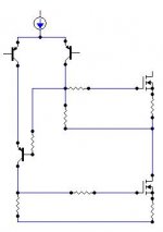
Sorry man I still don't get it. The negative rail FETs are driven by a constant current source T5 through T6 (half of the 2nd LTP). As T6's base swings negative T6 turns on harder swinging more current through R16. All T7 does is track the output swing setting its emitter 0.6 volts above that.
Can you describe your view in terms of voltages and current flows, so that I can follow you.
Cheers
Take a look at the attachment.....
viktor1986 said:
Yes!Why?
You look like a ..........younger TOM CRUISE in his Teens.......
Attachments
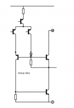
I also would not like to have T8 base connected to output.
Even when using a bipolar output.
Simply want to keep VAS stage transistors separate from output.
This is also shown in my earlier 'lineup-idea' attachment.
The diode shown in my attachment is not really needed.
I agree with Workhorse,
that T8 should have base connected to T7 collector (gate of upper MOSFET).
Attachments
Hi Quasi,
This configuration facilitates the Negative Rail Mosfets to Saturate efficiently when delivering near rail swings......As the output swings to the negative rails the base of cascode transistor also swiings to negative rails, but if it is connected to some higher elevation potential then it never saturates it self prematurely....that why I prefer it to connect it to gate drive collector terminal not at the output..
K a n w a r
I must apologise.
It's been very busy around here with other priorities.
The amp is still a happening thing and I intend to publish further news soon (May-June 06).
I have wound the auxillary windings on the power transformers for the stepped up rail and I have cut the heatsinks.
Next step is to drill the mounting holes, install the module and fire it up.
Cheers
I like your PSU board. I have considered using block bridges like that, but the holes has always put me off - them needing to be a slot. How do you make such slots efficiently?
Umm....I don't.
.
I loop some thick tinned wire through the hole in the spade terminal and solder, then thread both ends through a round hole in the PCB and solder.
The bridge spade terminals sit on top of the PCB.
Cheers
.
I loop some thick tinned wire through the hole in the spade terminal and solder, then thread both ends through a round hole in the PCB and solder.
The bridge spade terminals sit on top of the PCB.
Cheers
Hello all,
I've decided to build one of my next amps around this design, due to the recent abandonment of the Super Leach redesign. I intend to use a 120vct 2kVa toroid which will give +-84V rails for a 3 channel version of this amp to cover LCR in a 5.1, though I don't expect the center channel to load the toroid much at all. I assume both quasi's designs will work with these voltages, so it comes down to which sounds better. Any opinions?
Also, I'm leaning toward the 10-FET versions of each, though I preffer the other quasi amp since it has the integrated DC protection, is it easy to impliment it into this amp too?
Same boat as I am...
though I am not giving up on the super leach redesign and still hope jens to reconsiders.
I think quasi's design and the super leach shares the same power requirement.
I prefer quasi's other design which is proven.
though I am not giving up on the super leach redesign and still hope jens to reconsiders.
I think quasi's design and the super leach shares the same power requirement.
I prefer quasi's other design which is proven.
Yeah I do remember reading at one point that quasi still thought the first sounded better. I really wish jens would reconsider as well. I'm not a big fan of fets in general, having read that Leach converted one of his designs to use mosfets and reportedly didn't like the sound as much.
Quasi's design, although, does seem to provide more power given the voltages; never could figure out how Leach calulated power for his amp, claiming only 270W/8R with 85V rails.
At this point, I just want to build the thing, since my lower power 2 channel amp is complete and ready to be mated with the yet to be created 3 channel for ht use.
Who knows though. If I find I can do SMD work well enough, I wouldn't hesistate to ditch class AB and never look back in favor of class D.
Quasi's design, although, does seem to provide more power given the voltages; never could figure out how Leach calulated power for his amp, claiming only 270W/8R with 85V rails.
At this point, I just want to build the thing, since my lower power 2 channel amp is complete and ready to be mated with the yet to be created 3 channel for ht use.
Who knows though. If I find I can do SMD work well enough, I wouldn't hesistate to ditch class AB and never look back
in favor of class D.Although not as efficient, the other amp will be hard to beat in terms of sonics, but anything's possible with this amp. We will know in the near future.
The other amp has DC protection on the amp board and this may suit some constructors. The intention with this amp is to seperate the DC protection and provide two options.
1. A stand alone DC protection board to service two amp modules.
2. An integrated PCB that provides DC protection plus a slow turn on function for the main power supply.
These boards will be a snap to design as they will basically be a copy and paste of layouts I have already used.
PM650, with regard to your 2kva transformer you will need to wind an auxillary winding of about 8 volts above one of the 60 volts windings in order to provide the +10 volts or so extra drive required for this amp. If you do not want to do this then build the other amp.
As far as the other amp goes, with respect to proven design, I believe at least 20 or so stereo units have been successfully built.
Cheers Guys
Hi,
I think Leach's power figures are down to Vrail droop on continuous signals. They may also be limited by distortion rather than @ clipping. If Leach set a 0.1% limit, which is quite a common figure with manufacturers, it can reduce the apparent maximum power to 1 to 3 db below the peak power figures. Yes, looking at some numbers 400W to 450W power at clipping with a 10% duty cycle waveform may have been possible for a super leach on +-85Vdc rails when at quiescent.
BTW, the +-84Vdc for 120Vac CT is the resistively loaded voltage. The unloaded capacitively loaded voltage after the rectifer could be 4% (87.7Vdc) to 6% (89.4Vdc) higher and similarly could fall by 10% to 20% (about 71Vdc to 79Vdc or so) when fully loaded by all three channels (350W +350W +350W). That potentially is some SPL!
Good Post AndrewT,
The output powers quoted for amplifier modules should only be taken as approximate. The actual power achieved depends entirely on the power supply voltage rails and capabilty (size and quality).
I.e. a 200 watt module powered by a 50v 0 50v 1kva transformer / 100,000uF will deliver a lot more continous power than the same module powered by a 50v 0 50v 300va transformer / 10,000uF.
The best way to view an amp modules power rating is; how much continuous power the amp can deliver safely into a specific load before it blows up. Then work backwards to dimension the appropriate power supply. Caution though many amp modules rely on the power supply collapse AndrewT refers to for survival.
Cheers
Hi Quasi,
exactly, my Sugden Vrails = +-73Vdc & +-81Vdc runs 2pair 2sk225/j81 for both 8ohm and 4ohm loading. It relies on collapse to +-56Vdc when driving 8r. I have not tested it into 4r. The loading of 8ohm reactive at full rail voltage is way outside the 100mS SOAR. 4ohm reactive cannot be contemplated and yet one pair of monoblocks appears to have survived unrepaired for many years.
I have now modified them extensively to 4pair but the one major upgrade still needed is to replace the two EI 50Vac, 8Vac transformers (about 150 to 175VA) that power each monoblock. A toroid or bigger EI just will not fit.
Well thank-you both for the insight on power ratings. I suppose I will be going with the other amp since it seems to have all the features I'm looking for, efficiency asside.
I would be curious to know if you (quasi) have any figures for efficiency of the two amps, of even a rough guess of the difference between the two?
I would be curious to know if you (quasi) have any figures for efficiency of the two amps, of even a rough guess of the difference between the two?
Hi Quasi,
Where is your latest schematic, which is currently upgraded.....?
regards,
K a n w a r
Where is your latest schematic, which is currently upgraded.....?
regards,
K a n w a r
Bad Quasi;
-
Sadly I got distracted by other things, including helping some local friends build their own amps.
But I'll get there eventually and hopefully post some results.
Cheers
Quasi
-
Sadly I got distracted by other things, including helping some local friends build their own amps.
But I'll get there eventually and hopefully post some results.
Cheers
Quasi
- Status
- Not open for further replies.
- Home
- Amplifiers
- Solid State
- Another quasi-complementary design