Antec?
Here in Canada we have the well known Plitron, the cores for most of their transformers are from the east, they wind the rest on North American soil.
Perhaps Antec does the same? I don't really know.
djk said:I don't think those transformers are made in the USA.
Here in Canada we have the well known Plitron, the cores for most of their transformers are from the east, they wind the rest on North American soil.
Perhaps Antec does the same? I don't really know.
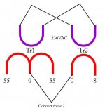
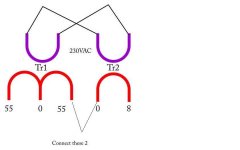
Yes you can run the secondary of that transformer in series with one of the secondaries of the main transformer. Run the primary in parallel with the main transformer primary.
Before you convert to DC you will need to measure the AC voltage to make sure it adds 8 volts to the main secondary voltage. If it subtracts 8 volts then the smaller transformer is connected out of phase so you must reverse it's secondary connection.
Cheers
Q
Before you convert to DC you will need to measure the AC voltage to make sure it adds 8 volts to the main secondary voltage. If it subtracts 8 volts then the smaller transformer is connected out of phase so you must reverse it's secondary connection.
Cheers
Q
Wasim said:What about the VA rating of the other transformer. Please also check this attachment is it fine If I start building it. I like the concept of making two separate stages
Regards
I like the concept of the two small PCBs too. Be aware though that this is an earlier version of the amp and I have not built or tested it. Please check the layout with the relevant schematic before you proceed.
Cheers
Q
Hi Quasi,
I am using 500VA 55 0 55 transformer and what about the VA rating of 9V Transformer? And will this enough for 3 Pair Fets board or should I go for 6 pair FEts?
Regards
I am using 500VA 55 0 55 transformer and what about the VA rating of 9V Transformer? And will this enough for 3 Pair Fets board or should I go for 6 pair FEts?
Regards
3VA 9Vac transformer will allow continuous DC current of upto 160mA.
Is that enough?
Iac =VA / Vac.
Idc = Iac / 2 for continuous output. Transient or low duty cycle current output from a transformer can be much higher.
If not enough then increase to 6VA. Or 18VA or 50VA or whatever you have to hand.
Is that enough?
Iac =VA / Vac.
Idc = Iac / 2 for continuous output. Transient or low duty cycle current output from a transformer can be much higher.
If not enough then increase to 6VA. Or 18VA or 50VA or whatever you have to hand.
"Iac =VA / Vac."
You forgot to figure in the power factor.
With the trend to large filter caps, the power factor may only be 0.5, so that doubles the (I^2)R losses.
Those losses are already so high the small transformer will probably have only a 20% regulation.
The front end of the amplifier runs class A, so we should probably figure on continuous duty cycle.
I would only run at 50% of rated VA with a continuous duty cycle, unless you like the transformer running at 85°C~100°C.
A 3VA 2x9VAC transformer de-rated at above should be good for about 40mA in a front-end supply, about 20mA per channel.
The Musical Concepts P3 cards for Hafler replacement draw about 20mA, and while designed to drive up to four pair (Hafler XL-600), they say you can run up to six pair of FETs with them.
No.
Iac is determined for a resistive test load to the manufacturer's spec limits. That could be temperature or regulation.
The DC current limit is based on the manufacturer's recommendation that the transformer be de-rated to ~ 70% of it's VA rating when feeding a capacitor input filter.
3VA 9Vac will be rated for 333mAac current into a resistive load. The output voltage will be 9Vac when at this loading and the transformer is fed with the rated mains input voltage.
The maximum continuous draw would be ~333/2 mAdc ~160mAdc from a capacitor input filter.
I agree that drawing this amount of power will make the transformer run very hot.
I agree that for continuous duty, the DC current should be <=50% of maximum rating.
The maximum continuous DC current should probably be limited to <=80mAdc. It's still going to be pretty warm and should be reliable if the ambient temperature is kept below the specification limit. This can be anywhere between 40degC and 70degC.
Where did 2x9Vac come from?
"No.
Iac is determined for a resistive test load to the manufacturer's spec limits. That could be temperature or regulation."
No, VA always takes into consideration the power factor as it causes more (I^2)R losses (affecting both temperature and regulation).
"The DC current limit is based on the manufacturer's recommendation that the transformer be de-rated to ~ 70% of it's VA rating when feeding a capacitor input filter."
No, 70% is assuming small capacitors, the larger ones audiophiles use make it more like 50%.
"This can be anywhere between 40degC and 70degC. "
Most small transformers are much higher than this at rated power, this being why they ned to be de-rated.
"I agree that for continuous duty, the DC current should be <=50% of maximum rating"
Yes, thank you.
"Where did 2x9Vac come from"
Most of these small transformers have dual secondary windings, very good for making our ± high voltage tiers. Total VA being the same for series or parallel use, of course.
40 to 70degC is ambient temperature (Ta) not transformer internal/insulation temperature nor temperature rise (DeltaT).djk said:"This can be anywhere between 40degC and 70degC. "
Most small transformers are much higher than this at rated power, this being why they ned to be de-rated.
I still don't agree on the sizing of the capacitance input filter affecting the ~70% de-rating specified by the manufacturers.
Can you point to a specific manufacturer that warns of excessive smoothing capacitance requiring a greater de-rating compared to that typical 70%.
Note before you spend too long on it, that our resultant recommendations are very similar.
3VA, 9Vac continuous current <=80mAdc.
3VA, 2x9Vac continuous current 40mA/winding.
The auxillary supply is for the input and driver stages of the amp. The total average current required by these while the amp is idling is about 32mA. Taking into account losses through the DC section lets say 50mA will be required. For two amp modules 100mA could be assumed.
So even the smallest commonly available transformer would be fine.
Another alternative would be to wind another secondary on the primary transformer and series connect this to one of the main secondaries. This is what I usually do because it simplifies wiring and saves on case real estate.
Cheers
Q
So even the smallest commonly available transformer would be fine.
Another alternative would be to wind another secondary on the primary transformer and series connect this to one of the main secondaries. This is what I usually do because it simplifies wiring and saves on case real estate.
Cheers
Q
- Status
- Not open for further replies.
- Home
- Amplifiers
- Solid State
- Another quasi-complementary design