Hi Quasi,
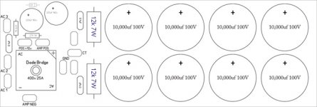
One question can I use one supply with 8 (10,000UF100V) caps to power up the both Acrk400 Amplifier. (See the diagram) or I must make the two separate Power Supplies to power up both amplifiers?
because I do not have much space in the enclosure.
Regards
One question can I use one supply with 8 (10,000UF100V) caps to power up the both Acrk400 Amplifier. (See the diagram) or I must make the two separate Power Supplies to power up both amplifiers?
because I do not have much space in the enclosure.
Regards
Attachments
Hi Quasi,
Thanks for the reply I will post my amplifier pictures tomorrow. I am still working on it.
Regards
Thanks for the reply I will post my amplifier pictures tomorrow. I am still working on it.
Regards
Hi Quasi,
In the enclosure I have two 12VDC fans already installed. Can I run 12VDC fans with 24VDC softstart power supply?
Regards
In the enclosure I have two 12VDC fans already installed. Can I run 12VDC fans with 24VDC softstart power supply?
Regards
Hi Wasim,
Yes you can run the two fans by connecting them is series or by using a series resistor to drop the voltage to each fan. You will need to find out how much current each fan draws and work out what value resistor you need. YOu will also need to make sure that the small power supply is big enough (enough VA).
Cheers
Q
Hi Qausi,
Thanks for the reply. Last night I finished the amplifiers and now I am waiting for the transformer. I will post pictures soon. I do need your help for setting up the amplifiers. Thanks again
Regards
Thanks for the reply. Last night I finished the amplifiers and now I am waiting for the transformer. I will post pictures soon. I do need your help for setting up the amplifiers. Thanks again
Regards
Hi Quasi,
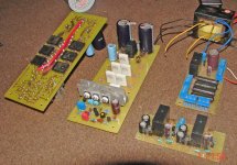
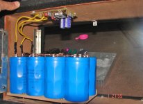
I have finished the amplifier. Just placing everything in the box. Just have look.
On the amplifier I just used three thing which are not in your diagram. The Power resistors I use are 0.5ohm 5w and The Caps I used are 440UF200V and the third thing is the 1845 transistors I used 2240. Is it fine will they effect the amplifier quality? I have those and I do not want to buy things 🙂 from the market but if you say I will get them.
The Out put FETs are IRFP460.
Regards
Wasim
Attachments
Hi Quasi,
I have tried to set the Bias of Acrk400 and I got problem with VR2 : I followed you posted procedure on your website.
The problem is that through 100R resistors I can control the voltage but it is not sticking on the one value and with in few min. the 100R resistors explode.
Through 100R 5w resistors on Positive rail I set the VR2 on 4V and after that it start increasing and it will go on and on.
what should i do? Plz help
VR1 is working fine though.
Regards
Wasim said:Hi Quasi,
I have tried to set the Bias of Acrk400 and I got problem with VR2 : I followed you posted procedure on your website.
The problem is that through 100R resistors I can control the voltage but it is not sticking on the one value and with in few min. the 100R resistors explode.
Through 100R 5w resistors on Positive rail I set the VR2 on 4V and after that it start increasing and it will go on and on.
what should i do? Plz help
VR1 is working fine though.
Regards
hi wasim,
may i jump in, i have through simiar problems most probable cause may be size of your heatsink and your biasing technique.if heat sink is too small the temprature will keep on rising of the heatsink and so the voltage through 100r resistance.the amp wont be idling and biasing cannot be set.2} if this is not the case check r16,r18 for their exact values with a meter.when the resister blew did you replaced it with anoher one and repowered the amp.are all mofets ok.when you see voltage is rising you should roll back the trimmer and give some time around 25-30 minutes the amp to idle.keep doing this until your voltages are stable.have you read the thread carefully.
ravs
be a vegeterian.man, most destructive creature of the world.
ravslanka said:
hi wasim,
may i jump in, i have through simiar problems most probable cause may be size of your heatsink and your biasing technique.if heat sink is too small the temprature will keep on rising of the heatsink and so the voltage through 100r resistance.the amp wont be idling and biasing cannot be set.2} if this is not the case check r16,r18 for their exact values with a meter.when the resister blew did you replaced it with anoher one and repowered the amp.are all mofets ok.when you see voltage is rising you should roll back the trimmer and give some time around 25-30 minutes the amp to idle.keep doing this until your voltages are stable.have you read the thread carefully.
ravs
be a vegeterian.man, most destructive creature of the world.
Hi Thanks for the reply. Yes you can always jump in 🙂
The R16 and R18 are with the same values as Quasi mentioned in the diagram on his website. The heat sink that have MJE350 heats up little. The heat sinks for output Fets are quite big. I used to use them for Nmos350 and they worked very well.
I replaced the 100R resistors again but it did the same with it. Burn them within few min.
Can you tell me how can i test my fets are working or not?
Regards
Wasim said:
Hi Thanks for the reply. Yes you can always jump in 🙂
The R16 and R18 are with the same values as Quasi mentioned in the diagram on his website. The heat sink that have MJE350 heats up little. The heat sinks for output Fets are quite big. I used to use them for Nmos350 and they worked very well.
I replaced the 100R resistors again but it did the same with it. Burn them within few min.
Can you tell me how can i test my fets are working or not?
Regards
hi wasim,
have you measred the dc offset. try disconnecting output coil and zobel network and rebias the amp.you can meaure voltage drop across the source resistors 0.47r to see if the fets are working.
go through this post 506
http://www.diyaudio.com/forums/showthread.php?postid=1611034#post1611034
ravs
be a vegeterian.man, most destructive creature of the world.
ravslanka said:
hi wasim,
have you measred the dc offset. try disconnecting output coil and zobel network and rebias the amp.you can meaure voltage drop across the source resistors 0.47r to see if the fets are working.
go through this post 506
http://www.diyaudio.com/forums/showthread.php?postid=1611034#post1611034
ravs
be a vegeterian.man, most destructive creature of the world.
Ok I do that what is Zobel network?
Wasim said:
Ok I do that what is Zobel network?
i mean to say r42 and c13.and please go through post 506
ravs,
be a vegeterian.man, most destructive creature of the world.
ravslanka said:
i mean to say r42 and c13.and please go through post 506
ravs,
be a vegeterian.man, most destructive creature of the world.
ok let me do it then I will let you know
Thanks
transistor replacement..
Hi all,
Can i replace trans mje15030/31 with FJPF1943/5200 to220F ( http://www.fairchildsemi.com/ds/FJ/FJPF1943.pdf ) ?
I`ve build nmos 200 and nmos350/500 (10 sets) and i`ve success build them all with no problem at all, i`m always do with lower volatage first time setup before power it with high voltage.
I`m going to build this system with 10 pair power trans to power up subwoofer 8 ohm 750 watts 18 inch, just wanna check few component might be upgrade for high current source such as mje340/350 and mje15030/31.
Actually i`m not build this thing for commercial and i`m just used it for myself at home, car and pajero, because sound system is my hobby and i love music.
Hope can get more info from expert users here for any suggestion. Exspecially quasi and other expert members.
Regards.
Hi ravslanka,
I did what you said. Remove the zobel network and tried to fix the bias thing. It is stable but still I can get minimum 20V across the 100ohm resistors 🙁. I could increase the voltage but could not reduce it. I changed the FETs also but get the same behavior. What should I do now
Regards
I did what you said. Remove the zobel network and tried to fix the bias thing. It is stable but still I can get minimum 20V across the 100ohm resistors 🙁. I could increase the voltage but could not reduce it. I changed the FETs also but get the same behavior. What should I do now
Regards
Wasim said:Hi ravslanka,
I did what you said. Remove the zobel network and tried to fix the bias thing. It is stable but still I can get minimum 20V across the 100ohm resistors 🙁. I could increase the voltage but could not reduce it. I changed the FETs also but get the same behavior. What should I do now
Regards
hi wasim,
did you checked the orientation of t4 ,diodes and zener diodes,output offset,there is something wrong .and did you read these posts
http://www.diyaudio.com/forums/showthread.php?postid=1611034#post1611034.
http://www.diyaudio.com/forums/showthread.php?postid=1615354#post1615354
ravs
be a vegeterian.man, most destructive creature of the world.
hi quasi and others,
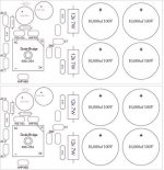
please check this modified layout pcb of Actrk400 / 600 as it is conventional type ie mosfets on one side.will it work or will it face oscilations or another problems.please comment.reason for this is easy acess of mosfets and easy to screw them.
thanks
ravs
be a vegeterian
please check this modified layout pcb of Actrk400 / 600 as it is conventional type ie mosfets on one side.will it work or will it face oscilations or another problems.please comment.reason for this is easy acess of mosfets and easy to screw them.
thanks
ravs
be a vegeterian
Attachments
Ravslanka: Remember to consider what happens if one rail fuse blows, but the other one doesn't. In some designs you get full DC on the output terminal, which can damage your speakers, and even start a fire.
Best regards
Lars Clausen
Best regards
Lars Clausen
- Status
- Not open for further replies.
- Home
- Amplifiers
- Solid State
- Another quasi-complementary design