Thanks Mr AndrewT, You are right. I misquoted transistor numbers. BC546 i.e.T4 in the circuit is used as diode here. I want to connect suitable value NTC Thermistor between +ve rail and emitter of T4. Any suggestion, will that combination work?
Thanks
Katiyar
Thanks
Katiyar
I think BUZ are Lateral mosFETs.
Quasi's designs use Vertical mosFETs and one uses BJT.
T4 provides temperature compensation for the T5 current.
Your proposal of replacing T4 with a thermistor completely changes the operation of the tempco.
Hi Andrew,
Can I use IRFP250 / IRFP260 instead of IRFP450 in Actrk 600 at 74-0-74 rail voltage.
Also BD139 instead of BC546 for temperature tracking?
How is temperature tracking transistor selected in a power amplifier?
BD139 would be much convenient for mounting on heat sink.
Regards.
Hi Andrew,
Can I use IRFP250 / IRFP260 instead of IRFP450 in Actrk 600 at 74-0-74 rail voltage.
Also BD139 instead of BC546 for temperature tracking?
How is temperature tracking transistor selected in a power amplifier?
BD139 would be much convenient for mounting on heat sink.
Regards.
BD139 is fine for temp tracking. Quasi himself said so.
I'm using it in 3 nmos200 amps.
Last edited:
I think Quasi is not so much active these days.
A DIYer curiosity.
From the Datasheet IRFP260 and IRFP450 looks similar except for the Vds and there could be many which I am not expert of.
Thanks Minek,
Any Idea what are the things to look for while deciding on specific transistor for temperature tracking.
I can assume Temperature coefficients mV/degree Celsius etc.
Considering the BC546 being used as diode.
I got the Base−Emitter Temperature Coefficient of BC546 from the datasheet from which I could vaguely figure out something but I did not see anything in BD139 datasheet.
I have no ideas about the changes you propose to Quasi's designs.
A DIYer curiosity.
From the Datasheet IRFP260 and IRFP450 looks similar except for the Vds and there could be many which I am not expert of.
BD139 is fine for temp tracking. Quasi himself said so.
I'm using it in 3 nmos200 amps.
Thanks Minek,
Any Idea what are the things to look for while deciding on specific transistor for temperature tracking.
I can assume Temperature coefficients mV/degree Celsius etc.
Considering the BC546 being used as diode.
I got the Base−Emitter Temperature Coefficient of BC546 from the datasheet from which I could vaguely figure out something but I did not see anything in BD139 datasheet.
Attachments
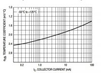
Look at your curve.
All BJT transistors will have a similar curve.
@ Ic=0.2mA tempco is -2.4mV/C
@ Ic=12mA tempco is -1.8mV/C
you can set which part of the curve and what value of tempco you need by setting the Ic.
You can do this for any BJT. The curve "shape" is the same. It just moves up or down a bit depending on the physical size of the die and the doping etc.
Thanks Andrew.
A newbie question,
From Datasheets it appears that Mosfets (e.gIRFP450) will fully conduct with 8-10 volts applied to the gates .
In many circuits I have seen Mosfet gates being clamped with less than 10 volt zenner diode for protection.
Then why is it needed rail to rail or more swinging VAS drivers for driving the same Fet gates?
If that was the case we could have used smaller transistors or an opamp to drive these mosfets .
I think there is something wrong with my assumptions ,Please clarify.
"Then why is it needed rail to rail or more swinging VAS drivers for driving the same Fet gates?"
If you want to drive ±50V out, you will need about ±58V to drive the gates (source follower).
If you want to drive ±50V out, you will need about ±58V to drive the gates (source follower).
I have built this Amplifier,powered it with DC+/-65 volts and 75 volt bias (1000VA transformer.) as required in schematic .
I have some doubts.
Maximum out put swing I am obtaining is 41 volt peak on speaker terminal into 4 ohms speaker ,using oscilloscope,beyond that sine wave distorts ,while power supply is at 65 volts.
Quiescent current requirement is somewhere around 300mA for a clean sine wave,anything less makes sine wave distort (in my system)
Mosfet used are IRFP 460.
please clarify what should I expect maximum voltage swing at speaker terminal .
I will click the screen shots soon.
Please advice .
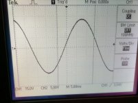
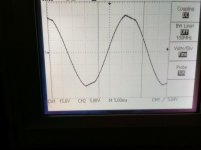
screen shots
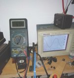
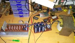
Please see the attached screen shot of wave form and assy.
Applied sine wave is 29 hz from PC
While doing the measurements ,Ac main voltage dropped to 197 volts hence the Vrail is +57 volts as in multimeter.
Is my Vpeak normal at speaker output ?
Please see the attached screen shot of wave form and assy.
Applied sine wave is 29 hz from PC
While doing the measurements ,Ac main voltage dropped to 197 volts hence the Vrail is +57 volts as in multimeter.
Is my Vpeak normal at speaker output ?
Attachments
If your mains supply is so variable, you will have difficulty relating performance to specifications. You don't mention your nominal supply voltage but assuming it is 220VAC, you have more than 10% drop and that must translate to more than 10% drop in peak output voltage too. It is good that you are successful so far, in having some output but are you using a dummy load?
An unloaded output stage may be good for a basic operational check but won't test the worth of modifications or parts choices you may have made, when that is complete and OK. The details of your changes are not clear from description so you will need to post the schematic showing your current modifications and parts substitutions as well as the original schematic again. That way, it will be possible to analyse what you have done, see possible errors and make suggestions with less difficulty.
There are explanations and guidelines for Hexfet or Vertical Mosfet design at Rod Elliott's ESP website. Read them carefully and note the possibilities of changes you made due to your circumstances or just curiosity. When you make subs and changes without full knowledge of how the circuit works and due consideration of the parts differences, you can well expect problems, unfortunately.
Using HEXFETs in High Fidelity Audio
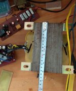
BTW, is the power transformer in the pics the same 1kVA rated? Even a toroidal transformer will be much larger, I think. A professional type E-I transformer will measure approximately 150 x 150 x150 mm. That is huge and mighty heavy. | RS Pro 1kVA Isolating Transformer, 230 V ac, 245 V ac, 400 V ac, 415 V ac Primary 1 x, 230V ac Secondary |
An unloaded output stage may be good for a basic operational check but won't test the worth of modifications or parts choices you may have made, when that is complete and OK. The details of your changes are not clear from description so you will need to post the schematic showing your current modifications and parts substitutions as well as the original schematic again. That way, it will be possible to analyse what you have done, see possible errors and make suggestions with less difficulty.
There are explanations and guidelines for Hexfet or Vertical Mosfet design at Rod Elliott's ESP website. Read them carefully and note the possibilities of changes you made due to your circumstances or just curiosity. When you make subs and changes without full knowledge of how the circuit works and due consideration of the parts differences, you can well expect problems, unfortunately.
Using HEXFETs in High Fidelity Audio
BTW, is the power transformer in the pics the same 1kVA rated? Even a toroidal transformer will be much larger, I think. A professional type E-I transformer will measure approximately 150 x 150 x150 mm. That is huge and mighty heavy. | RS Pro 1kVA Isolating Transformer, 230 V ac, 245 V ac, 400 V ac, 415 V ac Primary 1 x, 230V ac Secondary |
Hi Ian,
My Mains power line dropped while I was clicking pics,this happens in the evening time here in rural areas,unfortunately.
I was expecting near rail to rail output swing or at least within+/- 5 volt limit but my observation was clipping occurred nearly +/-15 volt less than v rails.
I have measured loaded as well as unloaded and out put clips at similar levels.
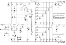
Schematics is the same from Quasi's website I am attaching it here for a review,no change of any components except output mosfets ,I have used IRFP460.
This is my first high power Amp,Building and powering up was cake walk thanks to Quasi,no smokes no surprises.The AMP is dead silent at power on but the quiescent current had to be around >250mA for distortion free waveform ( i.e 32 watts class A).I do it by oscilloscope/sine wave instead of series resistor method suggested by the Author.
TRafo is big enough I guess its 150mm at least 750+ Va I assume.pic attached.
My Mains power line dropped while I was clicking pics,this happens in the evening time here in rural areas,unfortunately.
I was expecting near rail to rail output swing or at least within+/- 5 volt limit but my observation was clipping occurred nearly +/-15 volt less than v rails.
I have measured loaded as well as unloaded and out put clips at similar levels.
Schematics is the same from Quasi's website I am attaching it here for a review,no change of any components except output mosfets ,I have used IRFP460.
This is my first high power Amp,Building and powering up was cake walk thanks to Quasi,no smokes no surprises.The AMP is dead silent at power on but the quiescent current had to be around >250mA for distortion free waveform ( i.e 32 watts class A).I do it by oscilloscope/sine wave instead of series resistor method suggested by the Author.
TRafo is big enough I guess its 150mm at least 750+ Va I assume.pic attached.
If your mains supply is so variable, you will have difficulty relating performance to specifications. You don't mention your nominal supply voltage but assuming it is 220VAC, you have more than 10% drop and that must translate to more than 10% drop in peak output voltage too. It is good that you are successful so far, in having some output but are you using a dummy load?
There are explanations and guidelines for Hexfet or Vertical Mosfet design at Rod Elliott's ESP website. Read them carefully and note the possibilities of changes you made due to your circumstances or just curiosity. When you make subs and changes without full knowledge of how the circuit works and due consideration of the parts differences, you can well expect problems, unfortunately.
Using HEXFETs in High Fidelity Audio
BTW, is the power transformer in the pics the same 1kVA rated? Even a toroidal transformer will be much larger, I think. A professional type E-I transformer will measure approximately 150 x 150 x150 mm. That is huge and mighty heavy. | RS Pro 1kVA Isolating Transformer, 230 V ac, 245 V ac, 400 V ac, 415 V ac Primary 1 x, 230V ac Secondary |
Attachments
Last edited:
OK, that's good that the difference is only in the output devices. If you read the article I linked, you will notice the emphasis on the loss of drive voltage to large Mosfet output stages - particulary Hexfets and even worse vertical types with high capacitance that may require a more powerful voltage amplifier stage to overcome the loss.
The signal voltage from the VAS stage determines output voltage so you should measure it with and without the output stage connected to verify that the VAS still functions correctly when loaded by the output stage. The disconnection should be the links from the collectors of both MJE350 transistors to the gate resistors.
Now, it should be possible to see on your scope what the VAS voltage is before and after, disconnection, thus checking the output stage and whether its devices are too heavy a load. By removing a couple of mosfet pairs, you should be able to verify the problem. The solution may involve different (recommended) output types but I can't advise on this.
Now, it should be possible to see on your scope what the VAS voltage is before and after, disconnection, thus checking the output stage and whether its devices are too heavy a load. By removing a couple of mosfet pairs, you should be able to verify the problem. The solution may involve different (recommended) output types but I can't advise on this.
Wouldn't disconnecting of output stages affect the feedback loop/voltage gain?
I will measure the Vas voltage and post the readings.
You are not disconnecting the output stage if the VAS outputs are terminated to the output node via R19, 20, 21. You simply have very little current available at the output. If you prefer, you could pull gate resistors R22-31 instead. Try pulling just a few pairs first.
Last edited:
A question this time. For the front end supply voltages, the positive rail is shown 10V higher than the negative. Do you have this arrangement or is your supply symmetric there too? If so, you could understand with this topology, why you don't have the full symmetric voltage swing.
I see that you say you have +/-65V rails with 75V "bias". Is that in agreement?
I see that you say you have +/-65V rails with 75V "bias". Is that in agreement?
Last edited:
A question this time. For the front end supply voltages, the positive rail is shown 10V higher than the negative. Do you have this arrangement or is your +/- 74V supply the same there too? If so, you could understand with this topology, why you don't have the full symmetric voltage swing.
I see that you say you have +/-65V rails with 75V "bias". Is that in agreement?
I have +10 volt additional tap from the trafo for the Bias.That was the main reason for trying this circuit.followed by simplicity is what attracted me to this.
With more than 32+ watts of Quiescent current, heatsink remains hot at idle periods and with such low output swing this amp gets very very Hot within minutes.
Does it actually comply being an H class amplifier ,I have noticed many times people calling this an H class amplifier.
Most of the H class amplifier have rail switchers and complicated circuits. To me it looks Class AB with additional bias.
You are not disconnecting the output stage if the VAS outputs are terminated to the output node via R19, 20, 21. You simply have very little current available at the output.
I get it. I will try to cut the track from R19, 17 to gates and measure.
This did not work,All the mosfets went full ON (probably stray charge of something turned them on with open gates),thankfully I have load bulb in primary of Trafo,nothing blew up.If you prefer, you could pull gate resistors R22-31 instead. Try pulling just a few pairs first.
Ah, I see too. It is a while since i looked at Hexfet designs. Apologies but thankfully you have quickly seen the mistake. As I recall, you also need to shunt the gates to off state (at the output node and negative supply rails respectively)
Without this step, the gates may still turn on without their 330R shunt resistors. However, I would appreciate comment from folk more experienced with this than I.
Incidentally, it's not a class H design. Classes G and H share the principle of variable rail voltages which are either switched between a number of cascaded supplies and output stages (class G) or continuously variable rail supplies (class H), according to output voltage demand. Either approach definitely lowers average idling current and increases the efficiency of high power linear amplifiers.
- Status
- Not open for further replies.
- Home
- Amplifiers
- Solid State
- Another quasi-complementary design