yes they are andrew,
i am going to re arrange them when i complete the amp.
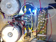
the wiring is not finalised yet please feel free to scrutinise 🙂
-Dan
i am going to re arrange them when i complete the amp.
the wiring is not finalised yet please feel free to scrutinise 🙂
-Dan
Hi,
it won't start with normal fuses there.
The fuses are normally fitted to the mains side feeding the primary and to the secondary side AFTER the smoothing.
Use a T rated mains fuse and a pair of F rated secondary fuses.
it won't start with normal fuses there.
The fuses are normally fitted to the mains side feeding the primary and to the secondary side AFTER the smoothing.
Use a T rated mains fuse and a pair of F rated secondary fuses.
Thanks for the advice andrew.
dont stress, I have "slow blow fuses" there.
and a fuse in the mains and on the board...
beginning to defeat the purpose of a low impedance supply really.
final wiring will be a mains fuse, and the on board fuses.
-Dan
dont stress, I have "slow blow fuses" there.
and a fuse in the mains and on the board...
beginning to defeat the purpose of a low impedance supply really.
final wiring will be a mains fuse, and the on board fuses.
-Dan
Hi Anthony,
The Trick for no thermal compensation is that in order to control the Function [Quiscent Bias]of Mosfet according to Temp & VCC variation we have to monitor the drain current and configure the mosfet into Voltage Control Current Source.......Also this will ensure accurate current sharing between parallel pairs......
regards,
Kanwar
Attachments

Hi Kanwar
Interesting....
The opamp shown could be replaced with discrete differential stage I imagine?
Email me and tell me more Kanwar 😉
Interesting....
The opamp shown could be replaced with discrete differential stage I imagine?
Email me and tell me more Kanwar 😉
Andrew,
I just reviewed your 20dB flick switch method for measureing the amp, Have you ever used this method yourself? did you use a normal sig gen with a rotary attenuator and click it between say 0 and 20dB ?
or did you rig something up ?
why do you not just start with the normal sig gen output pot at 0V and wind it to clipping and then wind it back down again fast ?
this process only takes a couple of seconds ? and you can visibly see on the cro when clipping occurs ?
Have you tried this method before ?
-Dan
Yes, I use this method all the time.danieljw said:Andrew,
I just reviewed your 20dB flick switch method for measureing the amp, Have you ever used this method yourself? did you use a normal sig gen with a rotary attenuator and click it between say 0 and 20dB ?
or did you rig something up ?
why do you not just start with the normal sig gen output pot at 0V and wind it to clipping and then wind it back down again fast ?
this process only takes a couple of seconds ? and you can visibly see on the cro when clipping occurs ?
Have you tried this method before ?
-Dan
The low quality chip based oscillator has a 0db and -20db switch as well as the level pot. This switch would allow 1W and 100W output (except I work with voltage rather than watts). Then adjust and try 0.98W and 98W until you find what you are looking for. Repeatable and quick.
I also use a switchable attenuator. I set the 12 switches to exactly match the amplifier gain. Then the output of the amplifier is at the same level as the output from the oscillator (within +-0.3%). The attenuator ranges from 0db to -60.05db in 0.05db steps. I can use the two extra -10db and -20db steps to cut the amp input even further. This tool allows an inaccurate DVM to compare similar voltages very accurately, I Think I can measure frequency response errors to +-0.02db from 100Hz to 100kHz. But it's laborious.
For near full power testing it is quick, but more importantly for checking the electrical side of a new amp it allows low temperature testing thus keeping stress down and reducing the risk of failure during the testing phase.
If I needed to check the cooling capacity of the heatsink and it's interface to the output devices then a longer timescale would be appropriate.
interesting,
so you usually use the max hold function on your DMM/DVM to capture the output? or do you watch the DMM/DVM display ?
-Dan
so you usually use the max hold function on your DMM/DVM to capture the output? or do you watch the DMM/DVM display ?
-Dan
My DVM doesn't have a max or peak hold.
I just read the value as soon as it settles.
I read the scope first to check my adjustment and switch back to -20db, then read the DVM at the next one second or so @ 0db.
I just read the value as soon as it settles.
I read the scope first to check my adjustment and switch back to -20db, then read the DVM at the next one second or so @ 0db.
Hi All,
First power test of my ACTRK600 today......
mainly to make sure everything is working correctly.
clipping is symetrical.
no ringing or oscillation is visible on the scope. (BW10 MHz)
using the method AndrewT posted with the attenuator switch.
The first power output figure I have measured so far is.....
505.6 Watts into an 8 Ohm resistive load
😀
-Dan
Hi,
thermal stress is low and reliability is high.
No failures during resistive testing due to over temperature.
If it does fail then YOU know it is for another reason.
Have you seen the clip develop on the scope in those first few hundred mS after switching to 0db? or are your capacitor banks depleted so quickly that the clipped waveform appears to be almost instant when the signal is adjusted just a little bit too high?
89.94Vpk into 8r0. Quite a bit of voltage drive.
Now, how well does it hold up into 4ohms?
-0.4dbV or -0.8dbV, or could it be as bad as -1dbV?
Here comes my pet theory.
if the voltage into half the intended speaker impedance falls badly then the amp struggles to produce accurate AND low bass in balance with the other frequencies.
Have you seen the clip develop on the scope in those first few hundred mS after switching to 0db? or are your capacitor banks depleted so quickly that the clipped waveform appears to be almost instant when the signal is adjusted just a little bit too high?
- good question.... more testing needed....
89.94Vpk into 8r0. Quite a bit of voltage drive.
Now, how well does it hold up into 4ohms?
-0.4dbV or -0.8dbV, or could it be as bad as -1dbV?
- also good question.... this will be very dependant on supply ability.... more testing to follow....
Here comes my pet theory.
if the voltage into half the intended speaker impedance falls badly then the amp struggles to produce accurate AND low bass in balance with the other frequencies.
- I would agree with your pet theory, and i would add power supply quality overall makes a big difference here. regardless of PSRR. but i guess my comment is really just obvious.
-Dan
Hi Dan,
you would be one of the few to agree with my pet theory.
Many builders vehemently disagree.
and then complain about lack of bass!
The cause of our disagreement is that many refuse to believe that the PSU, in part, determines the frequency response of the amplifier. Although I suspect it is a second order effect rather than a direct relationship to the low frequency bandwidth.
BTW,
testing into a half value resistor load is a lot less stressful than driving real signals into a reactive load, provided you keep the semiconductor junctions at sensible temperatures.
I was quite staggered at the 4r0 capability of a 3pair output stage running from a 40Vac transformer, 311W into 4r0 and only 0.4dbV down from the 8r0 result.
Hi Andrew,
My personal (simplified) opinion is if you start with a poor quality power supply it is a recipe for poor sound.
On the other hand if you have a supply which is sufficient or even in excess of the power rating required for a given amplifier you have a solid base to start building with.
My preference is to have a power supply which is over rated in terms of capacity.
-Dan
danieljw said:Hi All,
First power test of my ACTRK600 today......
mainly to make sure everything is working correctly.
clipping is symetrical.
no ringing or oscillation is visible on the scope. (BW10 MHz)
using the method AndrewT posted with the attenuator switch.
The first power output figure I have measured so far is.....
505.6 Watts into an 8 Ohm resistive load
😀
-Dan
Five hundred watts into 8 ohms is a remarkable achievement, meaning you have a very stiff power supply. You have basically achieved almost the theoretical maximum with your supply rails.
Pretty cool...
Cheers
Q
The Saint said:Hi Kanwar
Interesting....
The opamp shown could be replaced with discrete differential stage I imagine?
Hello brother,
yeah, the opamp can be very well replaced by discrete circuit such as differential circuit and also another type of VCCS which could be formed by small mosfet like 2N7000 or similar type......
I will email you about details shortly
regards,
Kanwar
- Status
- Not open for further replies.
- Home
- Amplifiers
- Solid State
- Another quasi-complementary design