Hi Andrew,
Thankyou for the detailed response.
I will wind on another secondary and use "RCRC" filtering per your advice.
I think a 105Vdc reg will complicate things too much, however if noise is a problem i will build a series pass regulator using a
lm series reg and a BJT.
For the 105Vdc supply "RCRC" filter I have some 400-450Vdc caps which are designed for use with offline switchmode supplies which rectify the 240V mains to approx 350dc. they are rated for 400Vdc working.
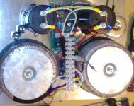
For the high current rails (+/- 92-95Vdc) unloaded the capacitors I am using (the large black caps in the pics) are designed to run at 100Vdc "working" voltage.
Over here apparently line voltage regulation is supposed to be +5% max so i am running pretty close to the line, However from measurement the supply runs at around 94Vdc unloaded.
-And your comment about the price of the high current filter caps
yes they are/were expensive!!!!
THX
-Dan
Thankyou for the detailed response.
I will wind on another secondary and use "RCRC" filtering per your advice.
I think a 105Vdc reg will complicate things too much, however if noise is a problem i will build a series pass regulator using a
lm series reg and a BJT.
For the 105Vdc supply "RCRC" filter I have some 400-450Vdc caps which are designed for use with offline switchmode supplies which rectify the 240V mains to approx 350dc. they are rated for 400Vdc working.
For the high current rails (+/- 92-95Vdc) unloaded the capacitors I am using (the large black caps in the pics) are designed to run at 100Vdc "working" voltage.
Over here apparently line voltage regulation is supposed to be +5% max so i am running pretty close to the line, However from measurement the supply runs at around 94Vdc unloaded.
-And your comment about the price of the high current filter caps
yes they are/were expensive!!!!
THX
-Dan
power up time.......
I think today is power up time.... for my ACTRK600's
I testing/building the supply.
The supply is at +/-94Vdc for the main rails and + 106Vdc for the Aux low current rail......
the filter i am using for the low current rail is two 450V 180uF caps for the RCRC section.. and a 100n "greencap" resistor values per ACTRK600 power supply form Quasi's design.
-Dan
(pic of supply working attached)
Attachments
I'll look to the north from my place. If I don't see a flash in the night sky, I'll know everything went ok.
Seriously, I know you've built amps before Dan, but please check everything before you power up the amp modules. You know, all the obvious stuff, checking the transistors are insulated from heatsinks, components right way round, power leads on right pins (yes I did mix'em once) etc.
Good luck & Cheers
Q
Hi Quasi!,
Did you see a flash ??
(after checking connections etc.)
I have done the whole quick quick power it up and see if it works thing.....
so far i have:
powered up one module and applied bias via 100 Ohm resistors in power rails... (1V across 100 Ohm) waited until this stabilised
applied 3.4V
checked amp operation it is working as an amplifier (did small jump for joy 🙂
powered down then powered up again with small fuse in neg rail and 10 Ohm resistor in pos rail... ended up with rail voltage
across 10 Ohm resistor... unsure why
possible **** connections (i am usinf clip leads)
Currently scratching my head, but will go over all connections and pcb etc etc to find what is going wrong.
-Dan
😀
Actually the resistor was 20W so it survived (extremely hot though)
it was only on for about 5-10s
-Dan
it was only on for about 5-10s
-Dan
after giving my 10 ohm resistor a hard time i backed off the bias so i did not own the largest semiconductor switch in adelaide,
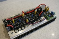
and "re-biased" the ACTRK600 I now have one channel up and running .
I am thrashing the living hell out of a test speaker as we speak🙂
sound is nice and clean 🙂 amp is just luke warm
Quasi, I understand why the bias is so complex after watching it work on the bargraph dmm...
overall - I am happy !!!!
😀 😀 😀
not too many from the amp yet so all is good!!!
will post more performance based figures when i get more time
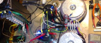
just if anyone is interested the loaded rail voltage is on the DMM screen bottom right of pic....
-Dan
and "re-biased" the ACTRK600 I now have one channel up and running .
I am thrashing the living hell out of a test speaker as we speak🙂
sound is nice and clean 🙂 amp is just luke warm
Quasi, I understand why the bias is so complex after watching it work on the bargraph dmm...
overall - I am happy !!!!
😀 😀 😀
not too many
from the amp yet so all is good!!!will post more performance based figures when i get more time
just if anyone is interested the loaded rail voltage is on the DMM screen bottom right of pic....
-Dan
Attachments
WHat do you think about Bryston Pushpull ?
http://www.bryston.ca/BrystonSite05/pdfs/SSTAmplifiers/9Bsst-Schematic12(2002-07,2004-06).pdf
Double quasi ?!
http://www.bryston.ca/BrystonSite05/pdfs/SSTAmplifiers/9Bsst-Schematic12(2002-07,2004-06).pdf
Double quasi ?!
Congratulations Dan
.
Well done on the build. What sort of power do you think it's pushing? There should be very little in loss across the output stage.
I do believe you have the built the first Actrk600 (probably more like an Actrk800) in the world.
Cheers
Q
.
Well done on the build. What sort of power do you think it's pushing? There should be very little in loss across the output stage.
I do believe you have the built the first Actrk600 (probably more like an Actrk800) in the world.
Cheers
Q
DIGORA said:WHat do you think about Bryston Pushpull ?
http://www.bryston.ca/BrystonSite05/pdfs/SSTAmplifiers/9Bsst-Schematic12(2002-07,2004-06).pdf
Double quasi ?!
Hi Digora, the link no work. "Double Quasi"? Well I am a Gemini !!
DIGORA said:WHat do you think about Bryston Pushpull ?
http://www.bryston.ca/BrystonSite05/pdfs/SSTAmplifiers/9Bsst-Schematic12(2002-07,2004-06).pdf
Double quasi ?!
edit link
DIGORA said:
edit link
That's a clever output stage. I never thought of doing that. Thanks for the link.
Cheers
Q
In fact I would like use this output stage 🙂
other SM :
http://www.bryston.ca/BrystonSite05/BrystonDocs.html
other SM :
http://www.bryston.ca/BrystonSite05/BrystonDocs.html
more like Thank YOU! Quasi,
first one in the world huh 🙂 i am proud, its good to build something which has a nice result.
I have not done a full load test yet... i will once i have all the wiring up to scratch or else my little clip leads will melt.
-Dan
first one in the world huh 🙂 i am proud, its good to build something which has a nice result.
I have not done a full load test yet... i will once i have all the wiring up to scratch or else my little clip leads will melt.
-Dan
Hi Digora,
That output stage looks like two amps in BTL per channel or somekind of linear h bridge motor driver 😀 nice specs though
interesting!
-Dan
That output stage looks like two amps in BTL per channel or somekind of linear h bridge motor driver 😀 nice specs though
interesting!
-Dan
danieljw said:I have not done a full load test yet... i will once i have all the wiring up to scratch or else my little clip leads will melt.
Aaah, the old melting clip lead phenomenon. When clip leads designed to pass one amp are asked to do much more.....
You probably know this, but whenever I buy a set of clip leads I peel back the plastic shrouds and solder the connections. The crimps are usually awful.
Cheers
Q
yeah they actually become useful for things over 1 amp if you solder in decent conductors 🙂
i was in the quick quick i wanna see what it sounds like frame of mind 😀
i was in the quick quick i wanna see what it sounds like frame of mind 😀
It's the classic Bryson quad output stage.danieljw said:Hi Digora,
That output stage looks like two amps in BTL per channel or somekind of linear h bridge motor driver 😀 nice specs though
interesting!
-Dan
One pair of emitter followers and one pair of compound followers (Sziklai) connected to the same driver pair.
Two quad sets make up the very high power version.
There was a Bryson clone thread a couple of years ago that briefly discussed this stage.
- Status
- Not open for further replies.
- Home
- Amplifiers
- Solid State
- Another quasi-complementary design