Hi,
then one must be blowing and the other must be sucking.
They must not both blow.
Remember to turn the sucking one around, do not reverse it's direction by swapping the leads.
Do you realise that the sucker will run hotter and this will shorten it's life?
then one must be blowing and the other must be sucking.
They must not both blow.
Remember to turn the sucking one around, do not reverse it's direction by swapping the leads.
Do you realise that the sucker will run hotter and this will shorten it's life?
Hi Andrew,
Thanks for the input, but the fans are in push pull.
I am aware one will get hotter.
-Dan
Thanks for the input, but the fans are in push pull.
I am aware one will get hotter.
-Dan
ACTRK600 getting closer...
Hi all,
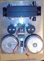
my ACTRK600 build is getting close to power up time....
currently i am just wiring up the power supply
***I HATE REMOVING THE ENAMEL FROM TRANSFORMER WINDINGS!!!!!!!!!!!!!!!!!!!!!!!!!***😡 😡 😡
Any how here are some pics........... 😀 😀 😀
Hi all,
my ACTRK600 build is getting close to power up time....
currently i am just wiring up the power supply
***I HATE REMOVING THE ENAMEL FROM TRANSFORMER WINDINGS!!!!!!!!!!!!!!!!!!!!!!!!!***😡 😡 😡
Any how here are some pics........... 😀 😀 😀
Attachments
Mr Quasi,
Will 12 DC regulated be ok for the additional low current VAS supply ?
any hints on biasing ????
- Dan🙂
Will 12 DC regulated be ok for the additional low current VAS supply ?
any hints on biasing ????
- Dan🙂
Hi,
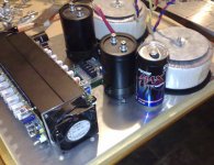
two transformers, two rectifiers and two smoothing capacitors.
How are you connecting these?
post 354 confirms ONLY two smoothing caps!
The extra rail is better done as an AC supply totem poled off the AC from the main transformer. Then rectify that high AC voltage and finally regulate it to [+Vrail + 9Vdc]. Yes, a high voltage regulator.
If you regulate to 9Vdc and then totem pole it on top of the modulated main Vrail supply, the "stiff" supply to the front end gets modulated with the output signal. I don't think that would help improve the sound quality.
Another alternative,
totem pole the 9Vac on the 50Vac. Rectify to 83Vdc. Then RC filter it, or even RCRC, to give the required unregulated DC voltage for the front end. The RC or RCRC will filter out much of the modulation coming from the main transformer winding. Watch the voltage on those little RCRC capacitors.
AndrewT said:two transformers, two rectifiers and two smoothings capacitors.
How are you connecting these?
Good point, I assumed the other 2 caps are not in the shot. 😀
BTW: I very nice build.
Nice Work Dan
Very nice work Dan,
In your case the first and second stages need about +105 volts and this should be referenced to Gnd. The easiest way to get this is by winding extra turns on your transformer secondary and half wave rectifying and smoothing as shown in the power supply schematic on my web site. Alternatively, to just prove the amp is working you can connect this stage to the main positive rail and sort it out later.
When you first set up for biasing, replace the two fuses with 100 ohm resistors. Then turn the biasing control so that you have maximum resistance between the positive rail and the emitter of T5.
Place a voltmeter across the 100 ohm resistor on the positive rail, switch on and adjust the trimpot until you see a voltage (about 1 volt) across it. Wait and watch the reading for a few minutes, it should continue to rise slowly. Once it seems to have settled adjust again to 3 or 4 volts. This will have set about 40 milliamps through the output stage. Pause here and connect a CRO to make sure the amp is working with a small signal. Do not consider the voltage across the 100 ohm resistor on the negative rail as bias current indication.
All being well switch off and remove the 100 watt 5 watt resistors and place a 1 amp fuse (not a 10 amp) in the negative rail fuse holder and a 10 ohm 5 watt resistor in the positive rail fuse holder. Back off the adjusting trimpot a bit before you turn on again.
Switch on and adjust the trimpot slowly, pausing and waiting to allow the amp to settle until you get about 1.8 volts across the 10 ohm resistor. This has set the output stage bias current to 180mA.
When this is done center the output using VR1, and do a final check on the bias. When you're happy, remove the 1 amp fuse and the 10 ohm resistor and replace both with 10 amp fuses.
This is a bit more tedious than most amps, but it's a characteristic of the simple design.
If you want, we can make a time to do it together.
Cheers
Q
danieljw said:Mr Quasi,
Will 12 DC regulated be ok for the additional low current VAS supply ?
any hints on biasing ????
- Dan🙂
Very nice work Dan,
In your case the first and second stages need about +105 volts and this should be referenced to Gnd. The easiest way to get this is by winding extra turns on your transformer secondary and half wave rectifying and smoothing as shown in the power supply schematic on my web site. Alternatively, to just prove the amp is working you can connect this stage to the main positive rail and sort it out later.
When you first set up for biasing, replace the two fuses with 100 ohm resistors. Then turn the biasing control so that you have maximum resistance between the positive rail and the emitter of T5.
Place a voltmeter across the 100 ohm resistor on the positive rail, switch on and adjust the trimpot until you see a voltage (about 1 volt) across it. Wait and watch the reading for a few minutes, it should continue to rise slowly. Once it seems to have settled adjust again to 3 or 4 volts. This will have set about 40 milliamps through the output stage. Pause here and connect a CRO to make sure the amp is working with a small signal. Do not consider the voltage across the 100 ohm resistor on the negative rail as bias current indication.
All being well switch off and remove the 100 watt 5 watt resistors and place a 1 amp fuse (not a 10 amp) in the negative rail fuse holder and a 10 ohm 5 watt resistor in the positive rail fuse holder. Back off the adjusting trimpot a bit before you turn on again.
Switch on and adjust the trimpot slowly, pausing and waiting to allow the amp to settle until you get about 1.8 volts across the 10 ohm resistor. This has set the output stage bias current to 180mA.
When this is done center the output using VR1, and do a final check on the bias. When you're happy, remove the 1 amp fuse and the 10 ohm resistor and replace both with 10 amp fuses.
This is a bit more tedious than most amps, but it's a characteristic of the simple design.
If you want, we can make a time to do it together.
Cheers
Q
Hi Andrew, Hi Greg,
thanks for the comments,
- each 1kVA transformer (65-0-65Vac secondary) has a bridge rectifier, bridge rectifier outputs will be parallel prior to the caps.
fairly standard supply, I would prefer a single 2kVA (or larger) toroid but i have these from another project.
- I am going to regulate the low current supply using a LM7812 or LM7810 (hoping to get away with LM7812
- I dont think the modulation will be a big issue, the amp PSRR will be the defining factor (correct me if i am off base here)
- I know only two filter caps !!!!!!!!! sacrelidge!!!
didnt you see the pepsi max can ? 😀
what i mean is they have enough ripple capacity 🙂
-Andrew I completely agree with your comments on RCRC filtering I will add it if necessary. 🙂
wish i had a bit more time to fire it all up this weekend !!!
-Dan
Intersting bias procedure Quasi,
I will let you know how i go!!!!!
I was still typing my post when yours arrived!!!!!
- to be honest i am doing about ten things at once 🙂
Ok, after reading that i guess the LM7810 or LM7812 supply floating on the +ve rail is out!!!!
I will have to start winding....
on this note does any one have a "trick" for removing enamel
from ENCu wires chemically ?
-Dan
You can reference to positive rail if you wish, and I've done so in the past. At high power though the ripple will be quite large and this is why I changed it to a gnd reference.
Good luck in the setup. By the way if you parrallel the bridges they may not share the current equally.
For removing enamel, I've used a tiny blowtorch in the past to burn it off and then I just clean up the copper.
Cheers
Q
Good luck in the setup. By the way if you parrallel the bridges they may not share the current equally.
For removing enamel, I've used a tiny blowtorch in the past to burn it off and then I just clean up the copper.
Cheers
Q
Thanks for the info Quasi,
Will have a go at the blow torch trick.
since this amp will be for high-ish power i will ref to ground.
& use AndrewT's suggestion regarding the RCRC filtering.
-Dan
Will have a go at the blow torch trick.
since this amp will be for high-ish power i will ref to ground.
& use AndrewT's suggestion regarding the RCRC filtering.
-Dan
Hi D,
the two toroids are probably bifilar wound.
1.) It would be better to parallel the two secondary windings in a transformer than to parallel the two transformers.
2.) If you want to rectify before paralleling then you will need 4 rectifiers.
3.) If you rectify after paralleling you only need 1 rectifier.
However, if you decide to totem pole the AC from the LV winding to the main AC winding you need to keep the AC voltage ends separate from the ground. This forces one to adopt the dual rectifier solution and create the zero volt point after the rectifiers. This then becomes the add-on to option 2.) above.
I see three options. You choose.
Hi Andrew,
My mistake in the earlier post talking about the supply where i said:
"- each 1kVA transformer (65-0-65Vac secondary) has a bridge rectifier, bridge rectifier outputs will be parallel prior to the caps.
fairly standard supply, I would prefer a single 2kVA (or larger) toroid but i have these from another project."
I meant windings of each transformer parallel prior to the rectifier.
Similar to option 1 you mentioned.
-Dan
Hi All,
Quasi, where you said
In your case the first and second stages need about +105 volts and this should be referenced to Gnd. The easiest way to get this is by winding extra turns on your transformer secondary and half wave rectifying and smoothing as shown in the power supply schematic on my web site. Alternatively, to just prove the amp is working you can connect this stage to the main positive rail and sort it out later.
are these turns added to the existing secondary windings feeding the pos side of the rectifier ??
or is it a completely seperate winding ?
-Dan
Hi AndrewT,
I appreciate your response,
So when you say "totem pole" the extra" 8-9Vac winding onto the secondary, do youmean - attach the start of this small low current winding to the end of the 65Vac winding and wind some more turns on ? then rectify it with gnd as the 0V ref ? then RCRC filter or 105V regulator ?
for my benefit, is the reasoning behind this config. to reduce the effects of the high current supply ripple/sag/noise by placing the low current supply in front of the high current rectification??
feel free to me if my question is too obvious 😀
-Dan
I appreciate your response,
So when you say "totem pole" the extra" 8-9Vac winding onto the secondary, do youmean - attach the start of this small low current winding to the end of the 65Vac winding and wind some more turns on ? then rectify it with gnd as the 0V ref ? then RCRC filter or 105V regulator ?
for my benefit, is the reasoning behind this config. to reduce the effects of the high current supply ripple/sag/noise by placing the low current supply in front of the high current rectification??
feel free to
me if my question is too obvious 😀 -Dan
That sounds like you understand it correctly.danieljw said:So when you say "totem pole" the extra" 8-9Vac winding onto the secondary, do you mean - attach the start of this small low current winding to the end of the 65Vac winding and wind some more turns on ? then rectify it with gnd as the 0V ref ? then RCRC filter or 105V regulator ? for my benefit, is the reasoning behind this config. to reduce the effects of the high current supply ripple/sag/noise by placing the low current supply in front of the high current rectification??
I would simply wind on a 8 or 9Vac secondary. Bring both ends out. Then using an insulated terminal strip add together the voltages you need. If you wind the extra in the wrong direction you will get 105-9Vac=96Vac, swap the 9Vac ends around. If you attach the end inside or to the transformer you cannot swap it around.
0.6mm diameter enamelled wire is good for 850mA of AC current. After rectification and smoothing that is <=420mAdc. 0.4mm wire gives <=180mAdc. Plenty for two channels of front end without the drivers.
At these very high voltages, it might be easier to forget regulation and go instead for RCRC. The front end voltage will swing with the main voltage but the modulation at audio frequencies and above will be attenuated to below audibility.
105Vdc +6% for mains variation. What caps can you use? Maybe motor run caps? Electrolytic or film. 200Vdc electros are generally not available with a good range of values. 160Vdc film are expensive and bulky. Can you afford main smoothing caps for this voltage? I reckon you'll need +-40mF/channel for 4ohm duty at 200Vdc these will cost a fortune.
Do you realise that the main smoothing caps could be 100Vdc if you reduced the 65Vac very slightly. What is the mains voltage tolerance (here it is +6%). What is the open circuit voltage of the transformer when it is fed with nominal mains voltage? You may find that reducing the voltage to 63Vac or 64Vac will allow 100Vdc caps. Remember that the caps MUST survive if you disconnect the amps or the rail fuses blow.
- Status
- Not open for further replies.
- Home
- Amplifiers
- Solid State
- Another quasi-complementary design