Thanks Gramme - The reason I segmented the ribbon was to avoid large ribbon excursion caused by air movement - due to bass drivers or some other breeze. John Whittaker talks about it in his "True Ribbon" writeup (although I can't find the exact reference now):
http://ldsg.snippets.org/ALSR/ribbons.html
John also references Linkwitz on the subject. The gist of the problem is that a four or six foot unsuported length of narrow and very light aluminum foil can easily be moved around by air currents. This will cause it to swing within (or perhaps even outside) the magnetic gap, with corresponding distortion. John said that he saw the effect with his ribbon and thought of it as a very serious, if not fatal, problem.
I expect to avoid it by having 5.25 inch segements. All seven segements are in series and there is only one transformer for the entire driver. There is a possibility that I could change this to use two transformers if I decided to do some type of power tapering.
There is a second, less important, reason; it's a lot easier to accurately cut and center seven 5.25 inch ribbons than one 36.75 inch ribbon. I can cut each segement with acceptable accuracy with nothing more than a straight edge a razor blade. I can only imagine how hard it is to cut and mount a much bigger ribbon.
Thanks for the PASS DIY heads up. I'll watch for it.
Denis
The magnets are .25 X .5 X 1.75", N40 Neodymium. They are magnetized through the thickness (i.e. the poles are on the .5" X 1.75" surfaces).
Hey what can I say.
They look wonderfull.
What a great job you did.
What did it all cost? Is it hard for someone to build such tweeters?
They look wonderfull.
What a great job you did.
What did it all cost? Is it hard for someone to build such tweeters?
promitheus - Thanks! The cost depends on if you are learning from my mistakes or reproducing them 🙂 . The cost of learning from my mistakes is not that bad (compared to buying commercial ribbons). The cost of building two 47" long tweeters (36.75" ribbon radiating area):
1. Magnets = $2.25 * 42 magnets = $157.5 + Ship
http://www.engconcepts.net/List_Of_Rectangle_Magnets.asp
2. Crossbar Steel = .75 X 1.5 X 3 ft = $16.5 + ship
http://www.onlinemetals.com/merchant.cfm?pid=9720&step=4&showunits=inches
3. Pole piece steel = .625 X .625 X 8 ' = $1.56 + ship
http://www.onlinemetals.com/merchant.cfm?pid=4794&step=4&showunits=inches
4. Aluminium foil .0005"= = $12.68 # ship
http://www.mcmaster.com/ #9060K34
5 = Transformer toroids = 2 x ~ $2.00 = $4.00 ship
http://www.bgmicro.com/shop.asp
6. Hardware + magnet wire + etc = ~ $10.00 + ship
7. etc. (epoxy, screws. fibergalss board, ...) = ~$10
Total = ~ $225 + ship
add another $100-200 if you want to make every mistake I've made (OR make your own equivalent mistakes).
Denis -
FYI:
I expect to try out my final ribbon tweeters this weekend.
Denis
promitheus - To answer your "is it hard?" question: It does NOT require a machine shop or an Electronic Engineering Master's degree to reproduce. You do have to be reasonably handy with cutting and tapping steel bars, soldering, as well as a having a reasonably steady hand ( to cut aluminium foil). Aside from these skills, anybody could do it.
Denis
Denis
dhenryp said:The reason I segmented the ribbon was to avoid large ribbon excursion caused by air movement - due to bass drivers or some other breeze.
Denis
Hi Denis,
Long ribbons like the Apogees inserted foam rubber ribbon stops between the magnets in 1 or 2 spots along the ribbon to reduce moving air and resonance issues. Using the full ribbon area gives higher efficiency. One continuous linesource removes comb filtering effects created by spaces between separate line array drivers. If your design is a tweeter and has a steep crossover above 1Khz, you will likely see very little ribbon stretch over time with your 0.0005" foil thickness.
Some ribbons uses a deep quarter round bezel in front of the ribbon for diffraction and directionality control, and this also blocked some air movements.
dhenryp said:
1. Magnets = $2.25 * 42 magnets = $157.5 + Ship
My math stinks. This should be:
1. Magnets = $2.25 * 42 magnets * 2 speakers = $189 + Ship
Hi Denis,
I want to second what was said by linesource. The ribbons I am building are about 68" long. They have 16 segments that are 4.25" long and there is one continuous run of .250" wide 5 micron foil. Every 4.25" I have a cross bar with a 1/8" thick plastic block that sits on the cross bar and supports the ribbon. My mistake in my post above was that I forgot that you were cutting your ribbon segments from the sheets you bought from mcmaster.
By the way, I understand that magnepan anchors their 2.5 micron ribbon with dots of adhesive directly to the faces of the ferrite magnet pole pieces. This gives the ribbon support and would also indicate that there is virtually no gap between the ribbon and the pole piece. One of the patents posted earlier on this thread stated that the gap width between the ribbon and the pole piece had a significant effect on distortion. Any opinions on this gap/distortion thing anyone?
As an aside, my ribbon project has been under construction since last spring. I am not expecting them to be complete until next September. Your project is very similar to mine and I have been very encouraged by your progress and results. I am looking forward to hearing about what they sound like.
Best Regards,
Graeme
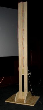
I've built a preliminary test stand for the ribbon and connected all the pieces and tried it out. I'm very happy with my early listening to the driver. It sounds "big". It projects a very detailed full sound (given that I'm only listening to >1.5k). I've done some preliminary measurements and I'm happy to say that the impedance through my DIY transformer is just about eight ohms (as calculated). Feeding it 2.88 volts produces about 95 db, which is about what I was hoping for. When I first connected it up I accidentally ran it full range. As long as I turned the bass knob on my receiver all the way down, the driver was happy with it and produced a surprisingly deep midrange. I'll have to experiment some more with crossover frequency.
Here is a picture of the test stand from the front. I've put on quarter round molding to help reduce diffraction (as linesource suggested). I have more quarter round that I intend to install on the back as well as some quarter inch wool felt to work on the back wave.
Here is a picture of the test stand from the front. I've put on quarter round molding to help reduce diffraction (as linesource suggested). I have more quarter round that I intend to install on the back as well as some quarter inch wool felt to work on the back wave.
Attachments
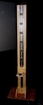
Here is the back, showing my transformer. I've wound it with tape to keep all the wire tight to the core.
Linesource, gl - Thanks for the info regarding periodically anchoring long ribbons to keep them under control. I had not read or thought about that.
Have you built special tooling to cut such long ribbons? How do you keep it evenly spaced throughout the whole length? My hat is off to both of you - I took the "easy" way out. One other advantage of segmenting my ribbon is that it provides places for the substantial back crosspieces that I need to close the magnetic circuit.
Attachments
Member
Joined 2003
Looking good Denis!
Here's the process I use for slitting ribbons up to 8'.
Stretch 3 layers of clear packaging tape the length of a glass table or mirror (MDF might work, but haven't tried it). Surface must be smooth and wrinkle free.
I use an Olfa "rotary cutter" available at Jo-Ann fabrics and a heavy aluminum straight edge I picked up at Lowe's or HD. I run the cutter perfectly perpendicular to the straight edge making the cut in one pass. I've found there is less chance of tearing if I pull up both sides of the cut at the same time. I haven't needed to use water with this process.
For the long ribbon "blowing in the breeze" a light resistive load (think 1-3 layers of grill cloth) behind the ribbon solves it for me.
If you want to suspend the ribbon at intervals along the length, I've found the "D" shaped hollow foam weather stripping works well. I like it better than "solid" foam strips.
What does the frequency response of your transformer look like at the ribbon termination (without crossover)?
Paul
Hi Paul,
You sound like you have a lot of experience with DIY ribbons. Do you have a website or forum thread where you discuss them? I would very interested to see what you have done. The same goes for linesource and gl (or anybody else). Do you have any information posted on what you have done? I've not seen much beyond John Whitaker, the Swedish forum, and the LaFolia planar where actual DIY hardware is shown.
With regards to my transformer bandwidth: I've tried to take measurements with my crude setup. It consists of a moderate quality VOM, a bottom of the line sine wave generator and an AudioSource Amp 2 amplifier. I fed in a constant 1v into the primary of the transformer (w/no crossover) and measured the output at the secondary. I went as low as 150 hz and still got full voltage (~170mv ~ to my turns ratio 5.6) at the secondary. I did not go below that because of the ribbon was not sounding happy. I went all the way up to 20K and the voltage had only dropped to 147mv. I went as high as 50k which is quite possibly more than my amp can handle. I was still getting about the same output voltage, but I would take that with a grain of salt. My generator output was drifting (I tried to compensate), my amp bandwidth is suspect and I have no idea what the AC scale on my meter does with 75k.
The bottom line: I think the transformer has adequate bandwidth for audio. FYI: based on my understanding of leakage inductance losses and the XL I measured (back a few pages) the bandwidth would be down 3db due to leakage inductance (only) way out there (~200k!?). I can't imagine that is correct or maybe there are other types of losses that I have not considered that would limit bandwidth before the leakage inductance losses.
One last note: I fooled around with the crossover and found I can play it significantly lower than my initial 1k 2cnd order. I've run it as low as 600hz first order and it sounds good at normal listening levels. It's probably lower (freq and order) than I would feel comfortable with in the final speaker. It does indicate that I have more leeway in the crossover than I expected. I could probably go as low as 750hz if I use a 3rd or 4th order filter.
Denis
Member
Joined 2003
Hi Denis,
No, not a lot of experience with true ribbons, though I did build some planars years ago. I've been at the ribbons for about six months but travel so much I don't get to spend much time on my hobby. No web page because I am still prototyping and don't have complete success yet.
I started working with ribbons because vertical dispersion of dome tweeters was TOO good (my system has strong horizontal dispersion, but intentionally limited vertically... Paul's test mules). Also, the dome mids are not as clean as the Excels so I decided to try to build a ribbon good below 800 Hz, or lower. Favoring lower excursion over horizontal dispersion, I've been working on 1" ribbons.
I quickly found "moving metal" is easy, "getting it right" is the hard part. At this point I've built 1" x 50", 60", and 30". For grins, I have run the longer ribbons as low as 20Hz...of course bass drums blast the ribbon completely out of the gap 🙂! I have a couple more motor designs to try before moving to a full system with woofers. So it will be a few months before a web page...Japan 3 weeks ago, London last week, Santiago this week, Japan again week after next...whew!
Keep up the good work!
Paul
would using dipole woofers help keep the bass waves from causing the ribbons to move since the low frequencies cancel out parrallel to the woofers (where the ribbon will be)?
If those are your mules, Paul, I can't wait to see you show ponies!Paul W said:
🙂
Chris8sirhC said:would using dipole woofers help keep the bass waves from causing the ribbons to move since the low frequencies cancel out parrallel to the woofers (where the ribbon will be)?
I think you are right Chris. The extent of the help probably depends on how good a null the dipole has. This would depend on, among other things, room placement and size and shape of the baffle.
Denis
Hi Denis,
From your progress and recent questions it seem that you will soon have to wander the audio wilderness to find your religion.
Do you believe in Dipole ribbons or Monopole ribbons?
You can test your faith by putting about 2" of very fluffy, open poly fill, followed by 4" of 703 or 705 fiberglass (or at least 4" of standard density poly fill) behind your ribbons and run your favorite tunes.
But master linesource, this grasshopper craves guidance🙂
I have planned to absorb that backwave to try out the ribbon as a monopole, but my room may demand it. I'm planning to use my ribbon in my home theater and this requires it be pretty close to the back and side walls. I'm afraid it may be too close for proper dipole operation. It may be far enough for the ribbon but I'm also planning a line source of mid-base drivers too. I will experiment with both.
Yesterday I ordered a Behringer measurement mike and preamp/mixer so I should be able to start taking proper measurements (JustMLS) relatively soon.
Thanks,
Denis
Hi Denis,
You asked a question on how I slit the aluminum accurately in long lengths. Well, I don't. I was given a roll of .25" wide 5 micron aluminum some time back by an aquaintance. The references you quote regarding slitting techniques are the only ones I've come across on the internet. I am using a narrow ribbon in order to maximize horizontal dispersion. The crossover frequency will be 2000Hz - 3000Hz depending on the mid-bass (dipole) driver I eventually choose.
Your ribbon project is one of the best ones I've seen on the internet. It combines simplicity with excellent results.
Thank you for posting your latest results. Things appear to be getting better all the time!
Best Regards,
Graeme
- Home
- Loudspeakers
- Planars & Exotics
- Another DIY Ribbon thread