More on Building
Dear Dhenryp,
I am probably a bit dense in these matters, but some questions pop into mind which you may have answered or implied in your answers:
1. Is your aluminium ribbon a full 36" long with crossbars to support the structure of the frame each 6 inches, OR is it 6 segments of ribbon each about 6 inches long with the ribbon fixed to the crossbars at approximately 6" intervals?
2. What was your sure-to-be-patented method of holding the magnets in place while the super glue dried?
3.Would this method allow expoxy to be used?
4. Would epoxy last longer (e.g. 20 years?)
Would I be wrong to think that these "true" ribbons should sound purer and perhaps go higher than the mylar/aluminium composite ribbons of the old Carver speakers, or their modern equivalents? I think that GRollins calls the latter type Magnetic Planars.
If so, this system should give unbelievable performance at an unbelievable price - and it really looks relatively easy for the handyman to put together.
I remain impressed +++ and would be happy with a simple diagram or two with a dimension or two to help the lead headed.
Finally, does anyone have any experience with Newform Research's composite ribbon drivers?
Regards,
George.
P.S. I think that the ideal distance between the magnets and the ribbons should be about one bee's dick 🙂 (diameter or length, your choice!)
Re: More on Building
>1. Is your aluminum ribbon a full 36" long with crossbars to >support the structure of the frame each 6 inches, OR is it 6 >segments of ribbon each about 6 inches long with the ribbon >fixed to the crossbars at approximately 6" intervals?
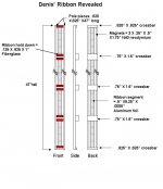
I've included a diagram. It is seven separate segments with seven separate ribbons.
>2. What was your sure-to-be-patented method of holding the >magnets in place while the super glue dried?
I HAVE patented my method (don't try to use it without my express written consent). I call my method "fingers". The crazy glue sticks in about 2 seconds.
>3.Would this method allow epoxy to be used?
"Fingers" (patent pending) is not practical for epoxy - even quick dry epoxy.
>4. Would epoxy last longer (e.g. 20 years?)
I'm not sure epoxy would be better. The magnets hold onto the poles VERY firmly so there is no chance of them falling off. The glue is only stopping the magnets from pushing away from each other and leaving a small (1/8") gap.
>Would I be wrong to think that these "true" ribbons should >sound purer and perhaps go higher than the mylar/aluminium >composite ribbons of the old Carver speakers, or their modern >equivalents? I think that GRollins calls the latter type Magnetic >Planars.
I can't really compare the sound to other planars because these are the only planars I've listened to. I think they sound great but that could just be pride playing tricks with my brain.
>I remain impressed +++ and would be happy with a simple >diagram or two with a dimension or two to help the lead >headed.
Done and thanks - see attached image.
>P.S. I think that the ideal distance between the magnets and >the ribbons should be about one bee's dick 🙂 (diameter or >length, your choice!)
"Bee's dick" is a phrase I have NEVER heard. It must be some special Aussie measurement standard (kinda like metric?). I suspect the gap is bigger than one BD (width or length) unless your bees down under are much bigger than I would like to encounter.
Regards,
Denis
>1. Is your aluminum ribbon a full 36" long with crossbars to >support the structure of the frame each 6 inches, OR is it 6 >segments of ribbon each about 6 inches long with the ribbon >fixed to the crossbars at approximately 6" intervals?
I've included a diagram. It is seven separate segments with seven separate ribbons.
>2. What was your sure-to-be-patented method of holding the >magnets in place while the super glue dried?
I HAVE patented my method (don't try to use it without my express written consent). I call my method "fingers". The crazy glue sticks in about 2 seconds.
>3.Would this method allow epoxy to be used?
"Fingers" (patent pending) is not practical for epoxy - even quick dry epoxy.
>4. Would epoxy last longer (e.g. 20 years?)
I'm not sure epoxy would be better. The magnets hold onto the poles VERY firmly so there is no chance of them falling off. The glue is only stopping the magnets from pushing away from each other and leaving a small (1/8") gap.
>Would I be wrong to think that these "true" ribbons should >sound purer and perhaps go higher than the mylar/aluminium >composite ribbons of the old Carver speakers, or their modern >equivalents? I think that GRollins calls the latter type Magnetic >Planars.
I can't really compare the sound to other planars because these are the only planars I've listened to. I think they sound great but that could just be pride playing tricks with my brain.
>I remain impressed +++ and would be happy with a simple >diagram or two with a dimension or two to help the lead >headed.
Done and thanks - see attached image.
>P.S. I think that the ideal distance between the magnets and >the ribbons should be about one bee's dick 🙂 (diameter or >length, your choice!)
"Bee's dick" is a phrase I have NEVER heard. It must be some special Aussie measurement standard (kinda like metric?). I suspect the gap is bigger than one BD (width or length) unless your bees down under are much bigger than I would like to encounter.
Regards,
Denis
Attachments
Hi Denis,
If you are in the mood for some experimenting, you may want to build up your second 48" chassis as one continuous magnet field to hold one continuous aluminum ribbon. You can experiment with using shims to space and center the ribbon, and can also get some very soft liquid rubber, liquid latex, or silicon to put small "dots" in the ribbon-magnet gap to manage this gap and reduce wind affects and resonances like the Magnepans.
Some supermarkets have very cheap generic aluminum foil that is 1/2 mill thick = 12.5 microns. Most brand name aluminum foil is 1 mil=25 micron, and the baking foil is 2 mil = 50 microns thick. When I cut AL foil I would put down a strip of plastic packing tape on an MDF board as a soft backing for the blade and use water to stick and lubricate the foil flat while cutting. I used both single edge razor blades and rotary cutters. A razor blade can work if you wet it before the cut and kept at a fixed accuate angle. There are several articles about cutting long ribbons on the web.
Hi Linesource,
I will certainly try a longer ribbon design but for the short term, I'm pretty much locked into the current design. I've already cut the steel for my second ribbon. These ribbons are going into a line array I'm designing and hope to start in the next week or two. If I don't settle on this design, it could end up on my pile of started - but never finished- speakers. The longer line is probably a project for next winter (after I remodel the family room🙂 )
WRT cutting steel: on the first ribbon I used a sawsall. It worked but it was slow and left an edge that kind of looked like a tree trunk chewed down by a beaver. It took lots of grinding to get it close to an acceptable finish. I bought a 10" abrasive chop saw blade (~$5) and stuck it on an old miter saw. It's much more accurate and leaves a better finish. It is still a pretty blunt instrument for cutting and generates lots of heat and sparks. I wouldn't want to use it on a production line but it was fine for cutting the handful of pieces I had left to do.
In this ribbon, the frame not only provides physical support but also completes the magnetic circuit between poles. Because of this, it was be made of a magnetic material. You could use aluminium but you would lose about 40% of the field strength in the gap. The 1018 steel I used is cheap, readily available and work just about as well as anything else without getting into exotic (i.e. expensive) alloys.
Denis
Denis
Where is the "Other Thread"
Dear DHenryp,
Now that I have started reading about these things, where is the "other DIY Ribbon thread" that you didn't want to hijack.
I also note that the frequency measurements you have put out are BETTER than the ones for other commercial drivers on the "snippets" site! (http://ldsg.snippets.org/ALSR/gallery.html)
Best regards,
George.
George,
The other thread is:
http://www.diyaudio.com/forums/showthread.php?s=&threadid=36559&highlight=
I'm pretty happy with the measurements so far but I would not put 100% faith in them yet. This is my first try at measuring and there are still a lot of JustMLS I've not yet sorted out.
I'm dissappointed that you did not include some new entomological colloquialism in your post🙂 You must at least gives us the the BD (length or width, your choice) to inches conversion factor next time!
Denis
Member
Joined 2003
LineSource,
I believe you once said you were crossing your 2" ribbons at 80 Hz, 8th order...correct?
At your max listening level, what is the maximum one-way excursion? Have you measured distortion at that excursion? If not, any audible distortion?
Paul
I believe you once said you were crossing your 2" ribbons at 80 Hz, 8th order...correct?
At your max listening level, what is the maximum one-way excursion? Have you measured distortion at that excursion? If not, any audible distortion?
Paul
Early Morning
Dear DHenryP,
1. I also may have missed this, but how have you made the mechanical and electrical attachments to your ribbon strip - Clamping/gluing/soldering?
2. I also presume that you set the strip in the middle of the gap's antero-posterior dimension. How did you organize that?
3. Is "crazy glue" some sort of methacrylate glue?
Essentially, I can see no reason why I klutz like myself couldn't build a pair of these. I also like the idea of a back and front quarter dowel to decrease diffraction.
How do you envisage using these in a complete system? Keep the cutoff frequency around 1000Hz? Do you reckon that you have enough mid-range oomph to keep the final design a two-way system with possibly a subwoofer available for very low bass?
Having checked out the links from the other pages, I am impressed with the absolute "simplicity" of your design. It almost seems too good to be true. I fear for the rest of the world's ribbon manufacturers.
Best regards,
George.
P.S. I shall be up at sparrow flatulence tomorrow to check for your thoughts.
Hi George:
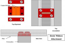
1. The ribbon is clamped. I've attached a diagram.
2. I'm going to use temporary spacers on the magnets to center the ribbon.
3. Yes
My ribbons are going into a line array. The ribbons will be next to a line of 14 PE Vifa buyout 299-432 4.5 mid bases. I expect to cross over with a 1.5k 4th order L-R active filter, biamped.
Thanks for the complements. It is a pretty straight forward design. The biggest part of the engineering was in the initial magnetic simulation and the transformer.
Regards,
Denis
Attachments
My First Ribbon
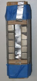
I was cleaning up my basement and came across my first ribbon "speaker". I'm posting it to give everybody a chuckle. As you can see, it was a humble collection of scrap steel, scrap wood, Scotch tape and some Neo magnets I bought last year with the intent of trying to build a ribbon driver (after coming across the other "DIY'ing Ribbon Driver" thread). The only thing that is recognizable is the pleated ribbon, which came out pretty good right out of the chute (it's beat up in the picture but trust me; it looked better originally).
How did it sound? - I did not dare connect it up to an amplifier so all I did was hook up a battery and make the ribbon click and convulse in the gap. That was enough encouragement to get me started on the prototype on page one.
Back to the present: I hope to complete the second ribbon this weekend (we'll see how much really gets done). I've got the design for the line array done and think I have a good shot to start in on it in a couple of weeks.
Denis
Attachments
gl said:Hi Denis,
Well I for one think your first ribbon looks very cool.
Graeme
My respect for you has dropped a notch...
🙂
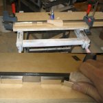
Well I did not get the second ribbon entirely constructed but I did get pretty far. I should be able to complete it this week. I thought I would show some pictures of how I get the magnets on the pole pieces. Getting a magnet on the pole piece is easy. Getting a magnet where you want it before the super glue catches is hard.🙂
The top picture shows the pole clamped to a folding work table. It's really important to get everything held in place before attaching the magnets - you don't want things moving around while you are trying to wrestle the magnet in place. The super glue I used is Loctite brand (I got mine at Lowes). It's got a neat delivery system that allows you to squeeze out glue with the bottle in any orientation. It comes in big bottles and the tip never clogs between uses.
The second picture shows me using a wooden wedge to control the magnet. The wedge allows me to get the end in the right place while keeping most of the magnet far enough away from the pole that it is not pulled out of my hand. I use two hands to do this. The picture shows one hand - the other is holding the camera. I first clean the pole and magnet with denatured alcohol to remove any oil. I put glue on the pole and then attach the magnets. The super glue gives you a second or two for final alignment.
Attachments
Here are a couple more construction pictures. The left shows the first step in bring to completed poles together. The attraction of two fully populated poles is intense you have to be careful. The first precaution is to tape wooden spacers to the magnets. These spacers are the same size as the gap. Then I put additional temporary spacers that will keep an extra ~2 inches between the poles. With the extra spacers it is possible to handle the second pole without crushing your fingers. I take the second pole and place it against the spacers and then remove spacer layers until the only one left is the gap spacer. At this range (1/2") , the poles will hurt if you get a finger caught. Ask me how I know. 
The second picture shows the two poles separated by the gap spacers. It also shows a crosspiece connected. As I said in a previous post, the cross pieces are so strongly attracted to the poles that, once attached, the only way to move them is to “nudge” them with a rubber hammer.
The second picture shows the two poles separated by the gap spacers. It also shows a crosspiece connected. As I said in a previous post, the cross pieces are so strongly attracted to the poles that, once attached, the only way to move them is to “nudge” them with a rubber hammer.
Attachments

Dear DHenryP
Nice pictures. Thanks.
1. Do you think that if one were to make a ribbon like your 6" prototype, that there would be advantage in two screws at each crosspiece. This would be difficult with the narrower crosspieces. In that design is there any disadvantage in using the wider crosspieces that you used in the 3' design?
2. In the 3' version, is there any advantage or disadvantage in using the wider crosspieces at each end of the pole pieces?
3. How much magnetic material is in those clamps?
Regards,
George.
>Dear DHenryP
>Nice pictures. Thanks.
>1. Do you think that if one were to make a ribbon like your 6" >prototype, that there would be advantage in two screws at >each crosspiece. This would be difficult with the narrower >crosspieces. In that design is there any disadvantage in using >the wider crosspieces that you used in the 3' design?
The machine screws are only used to hold the steel pieces together. A single screw at each corner is plenty. There might be a performance disadvantage of trying to squeeze in two screws; The steel is there to complete the magnetic path. Drilling holes reduces this pathway. Of course if the screws you use are magnetic, that will tend to compensate for the hole. They are less effective than solid steel as they are not as tightly coupled. I would stick with one screw per corner and make the screws smaller diameter. I used 1/4 inch (overkill). You could easily get away with #10 or # 8 screws.
FYI: On my big ribbon I put double screws in a couple cross pieces. I was worried about the frame racking (turning into a trapezoid) without them. I’m not convinced they are needed. It is very sturdy construction. Any bump is more likely to cause damage to the bumper (floor, knee, etc) than the bumpee ( ribbon frame).
>2. In the 3' version, is there any advantage or disadvantage in >using the wider crosspieces at each end of the pole pieces?
I don't think it hurts at all. In fact it might help a little as my femme simulation showed that crosspiece a little closer to saturation than I might like.
>3. How much magnetic material is in those clamps?
None - if you mean the red clamps I use to clamp the aluminum foil. Their purpose is to provide mechanical support for the ribbon and to electrically connect the multiple segments (hence the copper foil strips). In my original ribbon the 4-40 screws and lock washers were magnetic steel. I'm changing them to stainless steel because it's a pain to have them jumping into the gap all the time
>Regards,
>George. [/B][/QUOTE]
Regards,
Denis
PS
Once again, neither sparrow gas nor bee naught bits. Once again I am disappointed.
🙂
Power tapering ribbon
I was just thinking of a way to power taper my ribbons without special connections or crossovers. What about tapering using different ribbon masses for the different segments? In the center three segments I could use some of linesource's 5.8 micron foil and for the outer four segments I could use my thicker 12 micron foil. I could play with the thickness to get the right levels. The lower mass will give me extra output in the center segments. It will mess up the turns ratio a little but it's nothing I can't compensate for if it turns out I need to do anything. I'm planning to bi-amp the speaker so impedance for passive crossover purposes is not a consideration.
Does anyone have experience with tweeter power tapering? I suspect it may be less of an issue for me because of my somewhat abbreviated length (I'm talking about RIBBON length ).
).
Regards,
Denis
I was just thinking of a way to power taper my ribbons without special connections or crossovers. What about tapering using different ribbon masses for the different segments? In the center three segments I could use some of linesource's 5.8 micron foil and for the outer four segments I could use my thicker 12 micron foil. I could play with the thickness to get the right levels. The lower mass will give me extra output in the center segments. It will mess up the turns ratio a little but it's nothing I can't compensate for if it turns out I need to do anything. I'm planning to bi-amp the speaker so impedance for passive crossover purposes is not a consideration.
Does anyone have experience with tweeter power tapering? I suspect it may be less of an issue for me because of my somewhat abbreviated length (I'm talking about RIBBON length
).Regards,
Denis
Denis,
A different way to experiment with power tapering would be to place a wire (of a suitable resistance) in parallel with the uppermost and lowermost ribbon segments shunting part of the current flow.
You could experiment more easily with different power tapers.
I expect that your idea of using foil of different thickness might reduce the current flow through the entire ribbon by introducing higher resistance of the new, thinner, foil segments. Since all are in series, it would limit the current in all the segments.
In any case, a parallel wire of some suitable guage and/or length (to get the desired resistance) across the top and bottom segments is lots easier to experiment with than different ribbon materials and offers lots more range for adjustment.
Great Project, by the way. (I've been lurking and following since you started posting)
Joe L.
P.S.
If I just invented a new method of ribbon driver power tapering, royalies can be split between us 😀
- Home
- Loudspeakers
- Planars & Exotics
- Another DIY Ribbon thread