ingenious innovation
Hey Trenton, that's no longer a pivot arm anymore. I have to kick you out of this thread! Haha!
Simply amazing! You have done it. Congratulations!
I still can't wrap my head around those horizontal bearings or constraint bands. Since all the horizontal movements are on cams, it doesn't really pivot anymore. Even the vertical movement uses no pivot bearings! It's a form of constrained movement, not linear movement nor pivot movement, and yet almost frictionless!
What is the mounting distance from the center point of the fixed column to spindle?
What is the mounting distance from the center point of the fixed column to the stylus extended to the last groove?
Wouldn't that have to be longer than 110mm (95mm+15mm), right?
I don't see any visible anti-skating mechanism. It reminds me of Frank's ALTO tonearm mentioned in post #71 below. Is it the same concept?
The only precedence I can think of such invention is the Schuch string guided tonearm below and from video 001 and video 002 that uses no linear bearings nor pivot bearings. Sui generis! Obviously, Trenton's design is more stable as every contacting parts have the constraint layers going both directions to avoid any azimuth skewing.
Hey Trenton, that's no longer a pivot arm anymore. I have to kick you out of this thread! Haha!
Simply amazing! You have done it. Congratulations!
I still can't wrap my head around those horizontal bearings or constraint bands. Since all the horizontal movements are on cams, it doesn't really pivot anymore. Even the vertical movement uses no pivot bearings! It's a form of constrained movement, not linear movement nor pivot movement, and yet almost frictionless!
What is the mounting distance from the center point of the fixed column to spindle?
What is the mounting distance from the center point of the fixed column to the stylus extended to the last groove?
Wouldn't that have to be longer than 110mm (95mm+15mm), right?
I don't see any visible anti-skating mechanism. It reminds me of Frank's ALTO tonearm mentioned in post #71 below. Is it the same concept?
"The other advantage of this topology is the utterly simple way to generate a skating compensation force(decreasing towards the center). Move the shaft out of a perpendicular position and the offset mass will tend to find the lowest point. That's why the Alto's base can be"tilted"."
The only precedence I can think of such invention is the Schuch string guided tonearm below and from video 001 and video 002 that uses no linear bearings nor pivot bearings. Sui generis! Obviously, Trenton's design is more stable as every contacting parts have the constraint layers going both directions to avoid any azimuth skewing.
Thanks MarkI give up... no idea. Or,, perhaps a small deviation from strictly vertical so that the arm is lifted a wee bit when moving inward (resulting in a small outward-directed force)?
A little hint?

Last edited:
A little hint?
Hmm... a dice and a ribbon coil.
Is it to orient the direction in certain amount of the coiled constraint bands to generate an opposing torque or anti-skating force (or pointing the uncoiling side away from the spindle) and leave it to chance and hope for the best? 😀
What is the mounting distance from the center point of the fixed column to spindle?
What is the mounting distance from the center point of the fixed column to the stylus extended to the last groove?
Wouldn't that have to be longer than 110mm (95mm+15mm), right?
No getting rid of me. 🙂
Mounting distance is 170 mm for this version, I'm aware there would be some unsuitable geometries, but there are unlimited solutions to this topology and the maths can spit out another solution for whatever reasonable input values.
Effective length @1st groove = 149.93 mm
Effective length @last groove = 164.61 mm
I don't see any visible anti-skating mechanism.
Please see hint above.
It reminds me of Frank's ALTO tonearm Is it the same concept?
Sorry, I'm not familiar with that arm.
All my thanks go to you, as I would not have attempted this without the existence of your thread.
Hmm... a dice and a ribbon coil.
Is it to orient the direction in certain amount of the coiled constraint bands to generate an opposing torque or anti-skating force (or pointing the uncoiling side away from the spindle) and leave it to chance and hope for the best? 😀
😀 the dice was the closest thing at hand for scale.
That is one of the constraint bands before being stalled, it serves a dual purpose, a very tough constraint band and constant force spring to supply the counter torque.
Last edited:
anti-skating methods
The Schröder ALTO tonearm is simply what bambo alluded to early that "perhaps a small deviation from strictly vertical so that the arm is lifted (or tilted) a wee bit when moving inward (resulting in a small outward-directed force)?"
Now that you revealed you were using the coiled force to generate counter torque, the ALTO arm does NOT use the same anti-skating method as your design. Both are clever ideas.
I am just an armchair chronicler of all the interesting designs. You and others actually designed AND built them so I should thank you and them for giving this thread going beyond just academic musing and adding some "street cred" and eye candies!
Sorry, I'm not familiar with that arm.
The Schröder ALTO tonearm is simply what bambo alluded to early that "perhaps a small deviation from strictly vertical so that the arm is lifted (or tilted) a wee bit when moving inward (resulting in a small outward-directed force)?"
Now that you revealed you were using the coiled force to generate counter torque, the ALTO arm does NOT use the same anti-skating method as your design. Both are clever ideas.
All my thanks go to you, as I would not have attempted this without the existence of your thread.
I am just an armchair chronicler of all the interesting designs. You and others actually designed AND built them so I should thank you and them for giving this thread going beyond just academic musing and adding some "street cred" and eye candies!
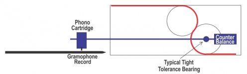
If condition of tangential pivot can be removed, I guess a working simple linear tonearm (With few compromises) can be made on Rolamite Mechanism, mentioned here #1637.
Basically a simple tonearm as shown in picture (Pretty basic drawing) where a rolling cylinder have axial hole to fit in a typical, high quality tight tolerance, almost frictionless bearing which will hold a tonearm wand. With cartridge and Counterbalance on either side.
I know the bearing would make noise but probably this design gets rid of skating force. And I think linear moving friction would be almost nil. The square box holding rolamite cylinders can be inclined slightly +/- if need arises.
I don't have means to make this tonearm. a different video : Rolamite 1 - YouTube
Regards
Attachments
I think Carlo probably has more experience at trying to make that work since #1360
If you can find him 😛
I've had no success applying compliant methods to linear TAs without traditional bearings.
Fixed pivot TAs have been easier. This is a possible solution.

Operation has not been confirmed yet.
If you can find him 😛
I've had no success applying compliant methods to linear TAs without traditional bearings.
Fixed pivot TAs have been easier. This is a possible solution.
Operation has not been confirmed yet.
Congratulation 2wice. you did it. A long run from the start, I remember well
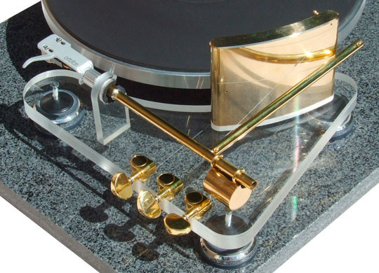
It seems - and it is - something completely new: in conception, geometry, movement transmission, and even materials are completely new for these applications.
And also the aesthetics are remarkable: seems more "Alien" than a Tone arm, and this is part of its charm; new concepts cannot resemble old ones.
carlo -(missing in action) I'm just trying to use the offset in the PLTs to keep the stylus centered into the groove, struggling on an evolution of my old 3Points arm. It'll take time, at least... you know what I mean
Thank you very much for your kind words, Carlo. It means a lot to me, coming from one of the Captains of this thread.
To you for the promotion on the field (..thread), 2wice: but the only quality I can boast is that of always trying, and not of being afraid of a dumb figure.
Usually it does not help to confer authority, and less to reach high career ranks.
c
Usually it does not help to confer authority, and less to reach high career ranks.
c
Pivoting tangential or not
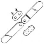
Hi directdriver, I actually think the cool design 2wice presented here still is pivoting, actually. One might consider the cylindrical elements rolling around each other, as part of a "polycentric hinge", or if you will a dual axes elbow joint. I attach a very simple exploded view picture of such a hinge. Now, if you make the hinge blades much thicker, get rid of the screws (on the 2 axes), loose the gearing teeth as well and then introduce the constraining ribbons to hold the whole hinge together, you end up with one of the dual axis hinges that 2wice uses in his design (he uses several of them actually). The pivots are 'hidden' inside, and on the circle-axes, of the cylindrical parts that roll around each other. So they are dual, and they are excentric, but pivots they still are.
enjoy your albums!
Mark
Hey Trenton, that's no longer a pivot arm anymore. I have to kick you out of this thread! Haha!
Hi directdriver, I actually think the cool design 2wice presented here still is pivoting, actually. One might consider the cylindrical elements rolling around each other, as part of a "polycentric hinge", or if you will a dual axes elbow joint. I attach a very simple exploded view picture of such a hinge. Now, if you make the hinge blades much thicker, get rid of the screws (on the 2 axes), loose the gearing teeth as well and then introduce the constraining ribbons to hold the whole hinge together, you end up with one of the dual axis hinges that 2wice uses in his design (he uses several of them actually). The pivots are 'hidden' inside, and on the circle-axes, of the cylindrical parts that roll around each other. So they are dual, and they are excentric, but pivots they still are.
enjoy your albums!
Mark
Attachments
Each of the cams have a pivot point, the coordinates of those, the mounting distance and the wand length are the input values for the maths to generate the curves of the working surfaces.
Having said previous, that I do not mind if someone built this arm for themselves and not for commerce, you might need this.
Maths
Having said previous, that I do not mind if someone built this arm for themselves and not for commerce, you might need this.
Maths
semantics
I get what you are saying but let's not get into debate with semantics here. First, I said it in jest with 2wice and meant to poke fun due to the reason that this thread had a history of going off topic. After all it existed for more than a decade of course discussion can be derailed sometimes. So, earlier I made it a point to remind members to stay on topic of discussing PIVOT designs, so no parallel trackers, not servos, no air-bearings, etc... as other great threads already cover those designs.
But the true innovation of 2wice's design is that it does not pivot in the traditional sense since it relies on multiple cams that don't pivot on a center point. It's a series of rolling elements with very little friction. I'm sure his math probably started out with a center pivot point and modify accordingly. My whole point, pun intended, is that it doesn't move in circular motion in the traditional sense. Of course, I believe the vertical arm does move with a central pivot point, no cam. The fact the entire arm's movements rely on constrained bands is innovation in itself and it's inspired by Jacob's ladder toy made it all the more ingenious and amusing! Visually it reminds me of a bumblebee with the stylus as the sting! 😀
Dtut is right that we are sensing a paradigm shift here in how we create bearings and how we create patterned movement with little friction. There are so many ways to skin a cat, indeed!
Hi directdriver, I actually think the cool design 2wice presented here still is pivoting, actually.
I get what you are saying but let's not get into debate with semantics here. First, I said it in jest with 2wice and meant to poke fun due to the reason that this thread had a history of going off topic. After all it existed for more than a decade of course discussion can be derailed sometimes. So, earlier I made it a point to remind members to stay on topic of discussing PIVOT designs, so no parallel trackers, not servos, no air-bearings, etc... as other great threads already cover those designs.
But the true innovation of 2wice's design is that it does not pivot in the traditional sense since it relies on multiple cams that don't pivot on a center point. It's a series of rolling elements with very little friction. I'm sure his math probably started out with a center pivot point and modify accordingly. My whole point, pun intended, is that it doesn't move in circular motion in the traditional sense. Of course, I believe the vertical arm does move with a central pivot point, no cam. The fact the entire arm's movements rely on constrained bands is innovation in itself and it's inspired by Jacob's ladder toy made it all the more ingenious and amusing! Visually it reminds me of a bumblebee with the stylus as the sting! 😀
Dtut is right that we are sensing a paradigm shift here in how we create bearings and how we create patterned movement with little friction. There are so many ways to skin a cat, indeed!
From the videos posted by 2wice, they look very convincing that the mechanism has very low friction. But it will be nice to see some kind of test to indicate its friction and to compare its friction to the friction of traditional pivot arms.
I've booked the VMC for Thursday to machine the last cam.
One of the things I enjoyed the most building this arm was being taught how to program and operated a milling machine.
One of the things I hate the most about building this arm is all the expensive tooling I've broken on the VMC making rookie mistakes.
This is a previous prototype with spring tensioners and probably the point I realised I've got a thing going, and I went from fully 3D printed parts to 3D printed cores and machined cams. I also cut the weight by 50%

The finish on the cams were ok, but I was using cheap import tooling.
The surface finish with the new tooling is like glass.
I've been very lucky to have a very talented machinist mentor.
Monday I will complete a Niffy pendulum with a micrometer to drive the rod, so I can get some numbers.
I still get a kick watching peoples faces when they have this in hand.
It is best described as, WTF! As it is impossible to bring to a standstill.

I have a build process in mind to cut the weight and up the stiffness even more.
One of the things I enjoyed the most building this arm was being taught how to program and operated a milling machine.
One of the things I hate the most about building this arm is all the expensive tooling I've broken on the VMC making rookie mistakes.
This is a previous prototype with spring tensioners and probably the point I realised I've got a thing going, and I went from fully 3D printed parts to 3D printed cores and machined cams. I also cut the weight by 50%
The finish on the cams were ok, but I was using cheap import tooling.
The surface finish with the new tooling is like glass.
I've been very lucky to have a very talented machinist mentor.
Monday I will complete a Niffy pendulum with a micrometer to drive the rod, so I can get some numbers.
I still get a kick watching peoples faces when they have this in hand.
It is best described as, WTF! As it is impossible to bring to a standstill.
I have a build process in mind to cut the weight and up the stiffness even more.
“It is impossible to bring to a standstill.” Name suggestion: The Mercury.
Welcome back, Carlo. I’d hoped the 2wice arm would bring you out of retirement.
Welcome back, Carlo. I’d hoped the 2wice arm would bring you out of retirement.
2wice,
I have been constantly impressed with the ingenuity displayed in this thread over the years. You have just kicked that up a full quantum level. Your band/rolling cam pivoting surfaces should theoretically result in virtually zero sticktion, which is a very significant design achievement.
Well done!
Ray K
- Home
- Source & Line
- Analogue Source
- Angling for 90° - tangential pivot tonearms