#2176 looks great, 2Wice - (once again)
I've tried to understand it's behavior on a graph, but without result. Do the 3 (or four) cams - or gears - share the same platform?
ciao - carlo
I've tried to understand it's behavior on a graph, but without result. Do the 3 (or four) cams - or gears - share the same platform?
ciao - carlo
Last edited:
Do the 3 (or four) cams - or gears - share the same platform?
Hi Carlo
No, not so easy to see, but the fixed and moving cams are connected with a cross bar, bottom leg of triangle with 2 single point contact jewel bearings.
The idler cam floats, is split into 2 cams sections. The bottom connected to the fixed cam and the upper to the moving cam.
They are constrained with the metal bands in 2 loops.
Theoretically, once the skate torque is compensated for, it would require the same amount of force/torque to move in or out.
The skate torque is compensated at the pivot as it is easier because the torque is reduced linearly approaching the spindle.
I have given up thinking of skate as a force vector at the stylus tip (it is), as the torque method helps simplify my design intent.
This video might make it clearer.
It is not of the design posted earlier but works on the same principle.
Only now the idler is offset and split, instead of 2 cam arcs combined in one cam.
The design in the video failed but not because of the geometry. I had the cams' laser cut and stacked to build the mechanism only. It ended up being impossible to manage the metal bands as it was all too small and the tensioning was a problem.
Also, getting the cams aligned was impossible even though I had guide holes in them.
Scaling it all up, redesigning the curves from some new maths and making planner surfaces on the cams to align easier.
I have modelled this, it works as intended with mechanical constraints only but not rendered as yet.
2wice, video link tells that access to it is limited, and so I'm not able to open and watch it.
2wice, video link tells that access to it is limited, and so I'm not able to open and watch it.
Try now, might have only worked for people logged in to YT.
Now i see - beautiful TA, great realization, 2wice: was it your previous idea, with rolamite cams?
Back to new design: I had noticed the double cam, and the triangle connecting the spindles: you say that the idler double cam "floats" = i.e. its spindle moves with respect to the others? how, using two cranks?
On my Rabbit I had the idea that SD and SF would cooperate in a variable way - see #1733 vector breakdown.
After a long time observation almost no bending could be seen, even less than on my Lil Casey linear, although it has just 140 milligrams of carriage's stiction. Maybe the SF has to appear only when the SD alone is not able to guide the PLT: being too weak, or dissipated on the constraint. On a Birch-type PLT the SD is used almost entirely for rotation, and this reduces skating to minimum, in spite of a virtual pivot more misaligned than in traditional pivoted ones.
Many affirm, or argue rightly that the SD should be reduced with lower peripheral speed (inner grooves) but with the pendulum test I saw a much smaller variation than from the musical content.
I understand the constructive difficulties: metal bands would be absolutely beyond my capabilities. I will follow your project with great interest
carlo
what's the reason of that bump on the wand - a resonances breaking zone?
Now i see - beautiful TA, great realization, 2wice: was it your previous idea, with rolamite cams?
Thank you. Yes that is correct
you say that the idler double cam "floats" = i.e. its spindle moves with respect to the others? how, using two cranks?
It floats in the sense that it is not "grounded" to the geometry by anything else other than the metals bands.
The fixed and moving cams are connected by a cam bar.
Float now seems the wrong term to use.
what's the reason of that bump on the wand - a resonances breaking zone?
No not really, I suspect you could resort to some marketing wank and call it so, but it is really just an aesthetic design choice and is actually a representation of a wave form going from the headshell to the counterweight. I won't use the design in the final TA.
I have a slight problem with calculating the effective mass, if I use the standard motion of inertia and distance squared formula then I think it excludes the mass of the idler and moving cams (as the horizontal and vertical pivots are not coincident) and with the wand so short the effective mass appears too little. On top of that it seems the effective mass of these types of TA changes as it translates. Including the LT. Not enough to be an issue and I'm probably wrong.
Does it make sense to calculate 2 effective mass values, one for horizontal to vertical pivot and another for the vertical pivot to stylus tip and add them or take the mean? Using this method means the effective mass does not change though.
kindly see if following has any merit...
since the moving cams are held by metal bands, the weight of cams will present uneven pressure on metal bands, and probably increase friction for movement of the whole arm. The cams should be as light as possible and if somehow frictioness support is provided at extreme end cam (Where tonearm is attached) it would be beneficial.
regards.
kindly see if following has any merit...
since the moving cams are held by metal bands, the weight of cams will present uneven pressure on metal bands, and probably increase friction for movement of the whole arm. The cams should be as light as possible and if somehow frictioness support is provided at extreme end cam (Where tonearm is attached) it would be beneficial.
regards.
These Compliant Rolling-Contact Element Mechanisms (CORE) as described by Larry Howell are very well understood and the friction characteristics are well-defined and very low. It is pure rolling contact friction, at least an order of magnitude smaller than sliding friction. Also, the pressure angle of the cams is 0, they exert no pressure on each other and never touch. They serve only as constraints to the geometry. The tension of the bands is not critical, but they should be equal if possible. It's not that important when the tension range where the cams will work is very wide, and used in commercial products every day. From atomic bomb triggers to air bags in the vehicles around us. Above all else they are reliable.
superofftopics
Tired of fumbling who knows where for infos read who knows when, here my small aid to simplify a bit the research.
attachment
These are only forums from our DiyAudio, and certainly many are missing: just a starting point.
Thanks in advance to whom wanting to enrich it with every kind of useful links (eg. patents etc). There are some good online sources talking about our favorite topics, together with several useless ones.
ciao a tutti - carlo
Attachments
Last edited:
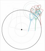
Hi 2wice, there is something I just can't understand in your graphs. (the one in black and red #2176)
fixed cam position: X or Y?
stylus position at the starting point: A or B?
with X position the C situation is ok, but B does not seem possible
with position Y the A situation is ok, but C does not seem possible
furthermore, given the direction of rotation of the shaft, the situation of the idler weel seems to me problematic (it would immediately lose contact)
Thanks in advance. Of course, if those graphs are made, as usual, to protect a possible patent, I don't expect an answer. Perfectly fair and understandable.
ciao Carlo
But that video is just a rendering? (it does not change the perspective)
Incredible realism, my compliments (from one who spent his life photographing products, trying hardly to make them look perfect)
Attachments

if those graphs are made, as usual, to protect a possible patent, I don't expect an answer. Perfectly fair and understandable.
Hi Carlo
I'll always be willing to share the information. There is a provisional patent, but for non-commercial use it will be fine. I'll even share the method of calculating the cams once it is confirmed to work. There are an infinite number of solutions to the geometry and some might be better than others.
There are programs to calculate these cams automatically from mechanical constraints only, but they cost more than my car. They offer an educational trial and I work in Maths and Science tuition, so I tried to use our company email, but they never replied.
I'm also trying to see if there is a way to counter skate just by changing the geometry so that added tension in the metal bands does the job, but it looks like a dead end ATM because it adds to the starting torque.
Please see this Video if that clears it up for you.
Great work 2wice, and that video couldn't be clearer - thanks.
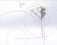
My graphic method drove me just to this point (attachment) but I could not see how motion was possible.
The torque, which at first sight seems to prevent it, should instead, together with the stylus drag, realize the rotation-translation, as in the video.
Now I really hope to see it realized: it doesn't seem simple, but neither impossible, considering the trajectory of the pivots.
really a new project+geometry. congratulations - carlo
Attachments
superofftopic 2
Two more well-known forums explored
Some thoughts: it is impressive how much was written about these topics (almost impossible not to reinvent the same wheels); however most of the posts concern the brands (this is better than that one...) or sound evaluations (wood sounds better than metal...). This incredibly narrows the number of useful posts, but increases exponentially the loss of time. (retirement's main goal? 🙂
Also added the thread's number of pages, useful for evaluating the consistence of a topic (even if one of the longest is for the TD124 mods!).
Next I will try to make an "index" of the longer threads that interest us, instead of wasting time with useless forums.
carlo
strange this silence on the new 2wice's project, that seems extremely stimulating both for the geometry and the innovative construction methods that it requires.
Attachments
strange this silence on the new 2wice's project, that seems extremely stimulating both for the geometry and the innovative construction methods that it requires.
I agree. The geometry is ingenious and despite its complexity the main linkages are still limited to only two pivots and the rest are considered to be parts of a guiding mechanism. And with all the rolling elements, it shouldn't be too hard to implement some kind of anti-skating device, if needed. A lot of potential and I hope it will be materialized into a real tonearm. Thanks for the posts and the video explanations, 2wice!
Attachments
- Home
- Source & Line
- Analogue Source
- Angling for 90° - tangential pivot tonearms