Member
Joined 2019
Check out segment at 2:20 and 3:35 and 4:47 and let us know what you think.
I do not 'think'. I see a disk eccentricity of about ±0.3 mm, well followed by the cartridge.
I don't think videos like this show us all that much. The cantilever doesn't appear to be deflected relative to the cartridge by much. If the cartridge has a 5mm long cantilever a 1° error would be generated from a deflection at the stylus of only 0.087mm. The cantilever in the video might be almost perfectly tangential, equally it might be deflected by the best part of a degree. The resolution of the video just isn't high enough to determine. If you can see the cantilever deflect relative to the cartridge with the naked eye by even the smallest amount then you have massive lateral error.
Niffy
Niffy
Member
Joined 2019
Flexible head shell will alter the arm/cartridge resonance frequency. But these two questions need to be further investigated in order to make judgments about the benefits of a flexible head shell.
1. Can a flexible head shell reduce the level of resonance frequency effectively?
2. Is it worth to make a flexible head shell at expense of rigidity of arm structrue?
I don’t prefer flexible head shells in most of cases. If you want to alter the resonance frequency, it is better to achieve it through designing the arm. If you want to reduce the level of resonance frequency, external damping at the bearing may be a better option. It is certainly not desirable to compromise the rigidity of the arm. Head shell is a such important part of a tone arm. I just can’t see anything would be better than a simple block of resonance resistant material.
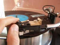
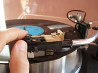
Here is a video to show how the cantilever of my Koetsu Rosewood Signature, a low compliance MC cartridge, was flexing on my 1" air bushing arm. The total mass of the arm is about 110 grams. It is a heavy arm. The LP is Ultimate Test LP 1kHz track. I expended the center hole to get the eccentricity. The silicone damping device was engaged.
YouTube
I could only catch the tip of the cantilever due to the long body of the cartridge.
YouTube
I could only catch the tip of the cantilever due to the long body of the cartridge.
back to mock up
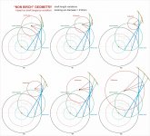
After last summer simulations of several geometries (#1917-18), now i went back to better explore that one based on imposing the shaft tangency to the groove, on a non-Thales arc.
These drawings were made to understand how it behaves, but without a real success: it is extremely sensitive to the diameter of the tracking arc and less to the length of the shaft, but what's the inherent rule? Only those two variants were examined, but there is also the rear shaft length, and maybe others.
Difficult to discuss this kind of PLT without knowing precise measures, since possible solutions are endless and very different from each other (shape and position of the guide): all geometrically accurate, but presumably with very different behaviors.
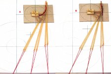
I made a couple of mockups with two very different guides for a rough string test*: the rotation is evident and fairly constant - more for A, something less for B.
In short, the offset pivots seem to do their usual damn work, inducing a variable skating as in Birch type.
Now I understand what Doug meant:
The chances of a DIY blue print replication of the Schroeder PLT being built are not very good, but a reasonably close working version based on the same principles? Yeah, that can happen.
carlo
*Ray K go-no-go string test - weight applied = 1gr tension + 10 gr rotation
After last summer simulations of several geometries (#1917-18), now i went back to better explore that one based on imposing the shaft tangency to the groove, on a non-Thales arc.
These drawings were made to understand how it behaves, but without a real success: it is extremely sensitive to the diameter of the tracking arc and less to the length of the shaft, but what's the inherent rule? Only those two variants were examined, but there is also the rear shaft length, and maybe others.
Difficult to discuss this kind of PLT without knowing precise measures, since possible solutions are endless and very different from each other (shape and position of the guide): all geometrically accurate, but presumably with very different behaviors.
I made a couple of mockups with two very different guides for a rough string test*: the rotation is evident and fairly constant - more for A, something less for B.
In short, the offset pivots seem to do their usual damn work, inducing a variable skating as in Birch type.
Now I understand what Doug meant:
The chances of a DIY blue print replication of the Schroeder PLT being built are not very good, but a reasonably close working version based on the same principles? Yeah, that can happen.
carlo
*Ray K go-no-go string test - weight applied = 1gr tension + 10 gr rotation
Attachments

Further thoughts about flexible head shells.
There are two claims about the benefits of a flexible head shells.
1. Reduce resonance frequency.
2. Change resonance frequency.
I am going to examine the first claim.
I assume following.
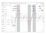
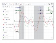
Y1=5 Hz, cartridge/arm resonance frequency(blue line)
Y2=10 Hz, flexible head shell/arm resonance frequency(green line)
Both levels of Y1 and Y2 are 2's.
So, Y1+Y2=cartridge+flexible head shell/arm resonance frequency(red dot line).
It is very clear that a flexible head shell doesn’t ALWAYS reduce the level of cartridge/arm resonance frequency. In fact, its combination may increase the level of cartridge+flexible head shell/arm resonance frequency. I indicated these increases in shadow areas in the diagram.
If the cartridge/arm frequency, Y1, is equal to the flexible head shell/arm frequency, Y2, and both frequencies are out of phase, Y1+Y2=0. In other words, cartridge+flexible head shell/arm resonance frequency doesn’t exist. Y2 cancels Y1.
In conclusion, a flexible head shell doesn’t ALWAYS reduce the level of resonance frequency. It may increase the level of resonance frequency.
There are two claims about the benefits of a flexible head shells.
1. Reduce resonance frequency.
2. Change resonance frequency.
I am going to examine the first claim.
I assume following.
Y1=5 Hz, cartridge/arm resonance frequency(blue line)
Y2=10 Hz, flexible head shell/arm resonance frequency(green line)
Both levels of Y1 and Y2 are 2's.
So, Y1+Y2=cartridge+flexible head shell/arm resonance frequency(red dot line).
It is very clear that a flexible head shell doesn’t ALWAYS reduce the level of cartridge/arm resonance frequency. In fact, its combination may increase the level of cartridge+flexible head shell/arm resonance frequency. I indicated these increases in shadow areas in the diagram.
If the cartridge/arm frequency, Y1, is equal to the flexible head shell/arm frequency, Y2, and both frequencies are out of phase, Y1+Y2=0. In other words, cartridge+flexible head shell/arm resonance frequency doesn’t exist. Y2 cancels Y1.
In conclusion, a flexible head shell doesn’t ALWAYS reduce the level of resonance frequency. It may increase the level of resonance frequency.
Attachments
Last edited:
In order for a rotating headshell(or a suspended counterweight for that matter) to counteract a given arm/cartridge resonance frequency, at least one parameter of this spring/mass system needs to be adjustable, usually the compliance of the spring. On some Japanese swivel headshells, there is an outrigger weight wich can be moved relative to the fulcrum, so the eff. mass of the moving part can be altered.
If it "just swivels" laterally at some random frequency, one does add an additional resonance which is the reason why most commercial implementations were dropped. It takes some knowledge/test record/equipment to adjust the Antiresonator for any given cartridge.
Most customers can't get the basic adjustments right, so...
The magnet/poleplate providing the centering for my swivel/rotating/whatever you want to call it - headshell serves yet another purpose. It pre-loads the "swivel"-bearing, so there is no chance for bearing chatter to occur.
The term resonances is thrown around here quite carelessly, I was only referring to the fundamental arm/cartridge resonance frequency in the lateral plane, not the type of exitation of structural resonances in the headshell/armwand/bearing structure. That is a different matter alltogether and well worth discussing, but maybe in another, separate thread...🙂
Cheerio,
Frank
Hi Frank,
Actually, whenever I used the words, resonance frequency, I strictly referred to cartridge/arm resonance frequency.
A cartridge and arm system is a spring system, so cartridge/arm resonance frequency exists. It is Y1 in my previous post. If an arm has cartridge/arm resonance frequency, it means that its head shell is a regular head shell, not flexible head shell.
Now, let’s install a flexible head shell and take the cartridge out of the equation. A flexible head shell and arm is a spring system, too. So, there is a flexible head shell/arm resonance frequency, I.e. Y2 in my previous post. From the video, I think the magnetic flexible head shell is a spring, too.
Finally, if I add a cartridge on a flexible head shell, there are two parts which bring the springiness into the system. The resonance frequency is actually combination of two frequencies. It is cartridge+flexible head shell/arm resonance frequency. That is Y1+Y2.
It is obvious that a flexible head shell may actually increases the level of resonance frequency.
Jim
Last edited:
Hi Jim,
"Actually, whenever I used the words, resonance frequency, I strictly referred to cartridge/arm resonance frequency."
I wasn't referring to you or your last couple of posts. And I wholeheartedly agree with your assessment regarding the possibility to increase the level at fres.
An Antiresonator works most efficiently when it is tuned to the resonance frequency in question(here, say, 6-14Hz). the application of damping to said resonator helps a little when the tuning isn't spot on, but still...
Anyway, that's off topic, so I'll stop here.
All the best,
Frank
These moving headshells are sold to cure many common, chronic ills that afflict most TAs.
attachment
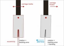
About the effects on the resonances Jim's graphs are more than evident; and the problem is that they do not remain on paper, but are directly applied to that of the musical signal. May I add two rough drawings about eccentricity overcoming and uniform motion on linear trackers? Here is what I think would happen when (or if) they rotate.
attachment
carlo
attachment
About the effects on the resonances Jim's graphs are more than evident; and the problem is that they do not remain on paper, but are directly applied to that of the musical signal. May I add two rough drawings about eccentricity overcoming and uniform motion on linear trackers? Here is what I think would happen when (or if) they rotate.
attachment
carlo
Attachments
Hi Jim,
"Actually, whenever I used the words, resonance frequency, I strictly referred to cartridge/arm resonance frequency."
I wasn't referring to you or your last couple of posts. And I wholeheartedly agree with your assessment regarding the possibility to increase the level at fres.
An Antiresonator works most efficiently when it is tuned to the resonance frequency in question(here, say, 6-14Hz). the application of damping to said resonator helps a little when the tuning isn't spot on, but still...
Anyway, that's off topic, so I'll stop here.
All the best,
Frank
Hi Frank,
Thanks for clarifying that! I misunderstood you.
Jim
pivot headshell
I've examined the work of stylus-brush behavior while playing LP from first to last track (setup as in #2138). Under the brush influence cartridge turns effortlessly. However, as a result of differend radius of the groove, as it decreases during playback, cartridge gradually turns too much. As a result, angular mistake is about 2degrees, not far from fixed shell. And so, the idea will not have a sense, at least with "normal" pivot arm with overhang and offset angle.🙁
Next experiment is with magnet stabilizer (no brush). As the stylus and pivot are coaxial to each other, I'm unable to detect any kind of pivot movement while playing record. For sure I will try with a test record, and with tuning the magnet arrangement by turning brass screw (on the top). For now it (pivot+magnets) seems to be not having any influence on cartridge and sound. Of course it should have with Nasotec kind of shell.
Attachments

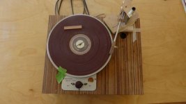
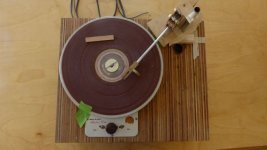
A while back, I got interested in the an idea DD has been advocating - separating the horizontal and vertical functions in a PLT. I thought, at first, that a good looking fairly simple TA might be possible, but difficulties became apparent quickly including keeping the subassemblies away from each other.
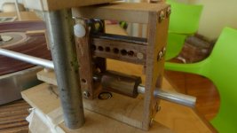
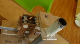
The photos show a model I built. You'll all notice my usual fit and finish, I'm sure.
I don't believe stylus drag is sufficient for PLTs so there was supposed to be a rotating arm to move carriage forward and control its position, but because the geometry I chose is wrong it just won't work.
Beyond that, I never satisfactorily solved the fundamental problem of side and axial forces on the linear bearings. The arm will rotate and the carriage will roll, but they don't like to do it at the same time.
I'm sure there are other better approaches to this idea and it is possible that exotic bearings and materials for the linear tracks could make this type of arm feasible, but the deeper I got into the project, the more convinced I became that rotational solutions are the easiest.
Attachments

Hi Doug, nice to talk about these things again with you: it seems that we have remained among the few "privileged" people (hard work + head banging) to have experienced first hand the problems of these TAs.
From the photos I understand too little, but it seems that this arm suffers from the same problem as the Syrinx
# 1521 I think i've made a big design mistake, not understanding that the same torque that generates the rotation is exactly the same that, acting orthogonally, hinder the linear bearing to slide (like moving a carriage by pushing from side). It's a matter of vectors, point of applications of the forces, not friction
I did not understand how your arm gets the advance, but maybe here too the lever torque blocks the linear bearing by side.
As you rightly notice the stylus drag is not absolutely sufficient for the task: the Syrinx mk2 #1531 had the linear bearing in front to avoid most of the leverage effect, but results were equally discouraging #1544.
Confirmed by measurements with the pendulum, which gave an SD of +- 1/4 of what everyone was talking about (data from calculations, or from the stepping down method) and behaved differently from usual beliefs (e.g. it seems quite independent on peripheral speed) -
...but the deeper I got into the project, the more convinced I became that rotational solutions are the easiest.
Now i'm pretty sure, too, that the extension must be get directly from the torque, without linear bearings, but how? The Syrinx string gadget worked great, if you didn't attach it to the linear bearing. And, if you think about it, that's what our Birch type do, too.
A true, extensible, Thales is the only solution to get a truly centered stylus: someone, someday will find the way. (hard work + head banging)
ciao carlo
Last edited:
I don't believe stylus drag is sufficient for PLTs
Hi Doug,
About a year ago, you complimented me for my design of a PLT, solely driven by the friction between the stylus and the rotating LP. Why do you now feel that stylus drag is not sufficient?
Assuming your carriage would roll, what would stop it from rolling all the way forward and thus causing the stylus to overshoot the point of tangency with the radius of the LP?
Sincerely,
Ralf
Very nice one !Hi Tournesol
maybe that question is more challenging than it seems. This is a thread for passive TAs, which I was referring - as said on #2033, and more on # 2048
Beyond my foggy hypothesis, Niffy gave the best answer, if not the only: perfectly centered disc, carriage's uniform motion, zero friction (0 ?) air bearings. No mention of pressurized air tubing, unfortunately.
But if you want to talk about active linears here is the same question, expressly made for those**
What the hell is going to happen to the cantilever, between one step and the next?
(Always talking about angles, or angels - how it's said in english?)
(attachment) i've tried this simulation, based on your graphic: if done correctly, hope it helps to investigate the problems around
https://www.diyaudio.com/forums/att...ng-90-tangential-pivot-tonearms-tourn-plt-mp4
The problem is, with passive systems, that the Friction forces on the disc will drive the diamond forward and we see the need for an "anti skating" to reduce this effect.
In my drawing, it has been placed in such a way that it opposes the rotation of the support disk of the arm, maximum at the external diameter of the record, canceling itself completely when the two axes are aligned with the central radius of the record.
But, as the friction forces depend on many factors, including the level of modulation, this solution seems to me acrobatic. While motorizing the system solves all the problems and is not complicated to create, with a worm and a motor to drive the small plate.
About arm resonances in the upper part of the spectrum, I obtained satisfactory results by simply sticking the head on the headshell with thick double-sided adhesives instead of screws.
Last edited:
Hi Ralf, I also congratulated you, renewing them here, for your absolutely revolutionary TA. But for me it doesn't seem to show that the stylus drag can advance a passive linear bearing guided PLT, since it needs a servo.
From the ball bearings layout your headshell seems to move laterally using mainly the side force (+ the amount generated by the SD with a suitable 10° Offset), followed by his servo rail. (i.e. > 3/4 of the entire TA)
To move a carriage (e.g. the linear ones use only the SF, the SD is totally lost in friction) is a difficult task for sure, but to allow an entire arm to follow a guide through a linear bearing seems quite impossible, at least after Doug's, and Syrinx, trials
Hi Tournesol, if my simulation correctly reproduced your scheme, at first sight shows two apparent problems:
the geometry is not very accurate (the 90° black line does not always pass through the spindle)
the control point Z position is anything but favorable: the stylus drag is a weak force (<<0.5 grams) and that angle would prevent the arm to follow its geometry, dissipating it instead in skating (like in my post 1544).
However these are only the impressions of one who has built 3-4 working Birch-types: and this is not a Birch-type. and in addition it is active.
Active ones are said to work always.
carlo
Last edited:
But for me it doesn't seem to show that the stylus drag can advance a passive linear bearing guided PLT, since it needs a servo.
Hello Carlo,
It is probably my fault for not having described my tone arm properly. The servo in my tone arm is not truly a servo, because it DOES NOT push the tone arm in any way. The tone arm is guided across the LP solely by the frictional drag between the stylus and the rotating LP! In fact, that frictional drag is so large, that I have to restrain the tone arm with the mentioned servo! I could achieve the same restraining force with a weight, hanging on a string over a pulley. And later this year I'll conduct some experiments in that direction.
Sincerely,
Ralf
- Home
- Source & Line
- Analogue Source
- Angling for 90° - tangential pivot tonearms