is it possible to model two bass drivers in HR, ie as per MTM design?
No.
I mean can you specify the location (line offset) of each (both) driver/s in the line?
Hornresp models multiple drivers as a single composite driver. At bass frequencies this is usually not a problem provided that the distance between the drivers is not too large. For example, at 100 Hz two drivers separated by 43 cm would still be only one-eighth of a wavelength apart.
Thanks David
I was interested in posing the question because in the simulation results the precise driver offset can cause quite significant response anomalies (in terms of a spike/cut at the first harmonic, at least with no filling applied); the simulation results suggests moving the driver 5mm or so each way can increase/reduce that spike considerably..
I'm not sure how much difference that can make to the overall frequency response smoothness in real life, especially once filling is applied, but I was just wondering as to best approach to applying an MTM design to the TL, ie whether to 'optimize' one driver according to the ideal offset ie around 1/3 TL length), and then locate the other driver say around 1/4 (determined by the minimum MTM driver spacing), or perhaps whether instead to locate the tweeter at the 'optimum' single-driver offset position, and then each driver will sit somewhat away from that position...?
Perhaps there is a rule of thumb to apply in this case?
I expect the answer may be "there is no simple answer" but I'm interested to learn from others' experience!
Thanks again for taking time to respond
I was just wondering as to best approach to applying an MTM design to the TL, ie whether to 'optimize' one driver according to the ideal offset ie around 1/3 TL length), and then locate the other driver say around 1/4 (determined by the minimum MTM driver spacing), or perhaps whether instead to locate the tweeter at the 'optimum' single-driver offset position, and then each driver will sit somewhat away from that position...?
Hi JVN01,
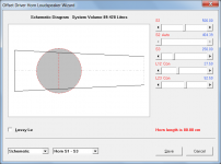
I think probably the best approach would be to find the optimum position for the composite driver, and then locate the two actual drivers equal distances either side of that optimum position.
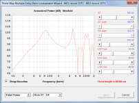
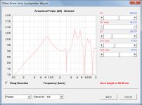
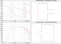
In an attempt to do a rough validity check of the above approach, I experimented using the Hornresp multiple entry horn model to specify a design having two separate drivers, and then compared the results against those for a composite driver positioned halfway between them.
As you can see from Attachments 2 and 4, the results are reasonably close up to about 200 Hz.
Kind regards,
David
Attachments
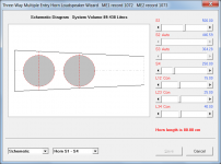
Standard practice I've always done, whether in MJK's sheets, Hornresp or just general design (and per what 'a certain person' taught me 😉 ) is simply to use the centrepoint between the drivers. Assuming they are within about 1/3 wavelength spacing at the mass-corner, they should sum to ~equivalent of a single (oblong) driver as far as loading the pipe is concerned, as the above neatly illustrates.
Last edited:
Thank you both for taking the time to respond - very helpful and most appreciated. David I hadn't realised it was possible to specify a pair of drivers in HR in that way, will give that a go 🙂
Hi JVN01,
I think probably the best approach would be to find the optimum position for the composite driver, and then locate the two actual drivers equal distances either side of that optimum position.
In an attempt to do a rough validity check of the above approach, I experimented using the Hornresp multiple entry horn model to specify a design having two separate drivers, and then compared the results against those for a composite driver positioned halfway between them.
As you can see from Attachments 2 and 4, the results are reasonably close up to about 200 Hz.
Kind regards,
David
Apologies David, one further Q, I tried looking for the Multiple Driver wizard in tools (as listed in the HR Help file) but can't seem to find it in any of the menus... any advice appreciated, cheers!
or perhaps if you can screenshot your Input Parameters screens for the examples above I can figure it out from there.. 🙂
thanks
thanks
I tried looking for the Multiple Driver wizard in tools but can't seem to find it in any of the menus
Hi JVN01,
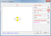
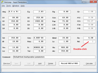
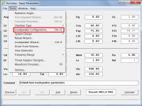
To specify multiple drivers in edit mode, either:
Option 1 - Select the Tools > Loudspeaker Configuration menu.
Option 2 - Press Ctrl+D.
Option 3 - Double-click on the disabled input box showing the driver configuration.
(I find Option 3 to be the quickest and easiest).
Kind regards,
David
Attachments
Neil. I wonder if you still participating in this forum.I discovered I had an error for the 4 ohm Dayton woofer - I had used a Vas value that I had arrived at with a calculator - but realized that Dayton Audio lists it. I had a value that was way too high, and now the response is very, very similar to the 8 ohm.
I also widened the last section from 3" to 3 3/4", and this results in the virtually flat shelf from 50Hz up to 200Hz, for both Dayton woofers. The extension frame at the top is for the Linaeum TLS tweeter. I have updated the images - I will attach them to this post.
In fact, I plugged in the SEAS Curv Cone U22REX/P-SL (H1659-08) woofer that I was considering - it is even lower Mms and lower Fs - but also lower Qts, and more than twice the cost. And the response with the Curv Cone woofer is virtually the same, in the same cabinet. The only functional difference - is the SPL level, based on the differing efficiencies between the three woofers.
They use different fill values - the Dayton 4 ohm and the SEAS Curv Cone uses 33 in the first two sections. And the Dayton 8 ohm uses 100 in the first section and 30 in the second.
I have studied your design and I try to reproduce your calculations. And I fail.
When I enter all driver parameters and line dimensions the result below 200Hz is similar. But between 220Hz and 300Hz I have a huge dip.
The only difference in the exported Hornresp files is a path length. In my model it is 0. In your model it is 75cm. The path length of 0.0 is displayed in the Acoustical Power window. Your screenshot shows a path lenght of 75 cm.
When I change the path length in the export file and re-import it, the response it similar to yours, no dip anymore between 220 and 300Hz.
I have looked through all Hornresp settings until I am blue in the face. I cannot find anywhere how to set the Path length. Can you help?
Attachments

It is "buried" - it is in the Loudspeaker Wizard (Control-E), and then select Power on the bottom left pulldown menu, then on the pulldown just to its right select Chamber. Then you will see Path at the bottom of the parameters on the right side.Neil. I wonder if you still participating in this forum.
I have studied your design and I try to reproduce your calculations. And I fail.
When I enter all driver parameters and line dimensions the result below 200Hz is similar. But between 220Hz and 300Hz I have a huge dip.
The only difference in the exported Hornresp files is a path length. In my model it is 0. In your model it is 75cm. The path length of 0.0 is displayed in the Acoustical Power window. Your screenshot shows a path lenght of 75 cm.
When I change the path length in the export file and re-import it, the response it similar to yours, no dip anymore between 220 and 300Hz.
I have looked through all Hornresp settings until I am blue in the face. I cannot find anywhere how to set the Path length. Can you help?
You have to have the actual dimensions of the cabinet you are designing, in order to get the path length - on the outside of the cabinet, from the center of the woofer to the center of the terminus opening.
And yes, it smooths out the response in a big way, because of the phase on the inside vs the phase on the outside.
I have built a second design with a SB Acoustics 8" woofer that I like a lot better than the Dayton Audio. It has an F3 of 27Hz, in the version I built - and I have tweaked it down to 25Hz for the next time I build it. And I just started a standmount speaker using a 6" SB Acoustics, with an F3 of 33.2Hz.
Thanks! It is there all right. I was in that window and that menu and still must have overlooked it. It must be the font size on my screen, or my age.It is "buried" - it is in the Loudspeaker Wizard (Control-E), and then select Power on the bottom left pulldown menu, then on the pulldown just to its right select Chamber. Then you will see Path at the bottom of the parameters on the right side.
You have to have the actual dimensions of the cabinet you are designing, in order to get the path length - on the outside of the cabinet, from the center of the woofer to the center of the terminus opening.
And yes, it smooths out the response in a big way, because of the phase on the inside vs the phase on the outside.
I have built a second design with a SB Acoustics 8" woofer that I like a lot better than the Dayton Audio. It has an F3 of 27Hz, in the version I built - and I have tweaked it down to 25Hz for the next time I build it. And I just started a standmount speaker using a 6" SB Acoustics, with an F3 of 33.2Hz.
And yes, it totally smooths the response.
Can anyone elaborate on this?In a transmission line loudspeaker, the sound from the rear of the cone is transmitted through a quarter wave tube. This is different from a vented box, as a transmission line is only delayed ninety degrees. Some may prefer the sound of a TL to a vented box, due to this aspect.
I cant see any real difference between ported and TL If the response (fundamental) is made to be roughly the same in Hornresp. Should this not show up in the sim?
Except that it seems to me that with the same driver getting the same response from a TL and a reflex box is extremely unlikely IMO, so you are likely erring some way if you are getting that result.
dave
dave
Compare the phase response.........huge difference in the cab's pass band where it counts, i.e. below the driver's upper mass corner [Fhm] = 2*Fs/Qts'
[Qts']: [Qts] + any added series resistance [Rs]: http://www.mh-audio.nl/Calculators/newqts.html
[Rs] = 0.5 ohm minimum for wiring, so may be higher if a super small gauge is used as a series resistor plus any added resistance from an XO/whatever.
[Qts']: [Qts] + any added series resistance [Rs]: http://www.mh-audio.nl/Calculators/newqts.html
[Rs] = 0.5 ohm minimum for wiring, so may be higher if a super small gauge is used as a series resistor plus any added resistance from an XO/whatever.
It's very likely im messing something up.
I dont see a major difference but ratio of group delay to efficiency appears to be slightly better for TL, scaling in Hornresp does also make it easy to miss things.
here is an example - The driver is ROSSO-12MW300, grey is TL, red is ported box attempting to match it (ignore impossible driver placement for ported, it doesn't impact the response)

Not sure if relevant to the discussion Dr MJK recently added to his body of work with a paper reconciling alignments for TLs and bass reflex enclosures if I read it correctly. My brain hurts from the math so maybe off track. engineers and those competent in physics may be able to shed light.
http://www.quarter-wave.com/TLs/TL_Alignments.pdf
http://www.quarter-wave.com/TLs/TL_Alignments.pdf
Not much to shed light on really, it's the typically erudite write-up you would expect from Martin & should be more-or-less essential reading for anybody interested in the subject, just like the rest of the material on his site.
The one thing I would slightly (slightly) disagree with is the assertion that for comparative purposes the boxes must share the same Vb and Fb for an apples / apples comparison. While that's true if you are using the physical box volume and system tuning frequency as your comparative baseline, you could raise the point that because the TL (or at least the type of TL he's referring to in that article), is likely to use a higher level of damping than the T/S aligned vented box, you are going into it from the outset knowing that its acoustic alignment will be more highly damped under those conditions. Ergo, an alternate perspective would be to use equivalent acoustic alignments as the comparative baseline (which would mandate the same Fb but an altered Vb between the two boxes to hit said alignment target, or as near as possible). He discusses this at length in the text of course and I'm not disagreeing with the data / content, just noting that the apples / apples (or apples / oranges) aspect mentioned in the conclusion will differ depending on what criteria you're using or the perspective you're approaching it from.
The one thing I would slightly (slightly) disagree with is the assertion that for comparative purposes the boxes must share the same Vb and Fb for an apples / apples comparison. While that's true if you are using the physical box volume and system tuning frequency as your comparative baseline, you could raise the point that because the TL (or at least the type of TL he's referring to in that article), is likely to use a higher level of damping than the T/S aligned vented box, you are going into it from the outset knowing that its acoustic alignment will be more highly damped under those conditions. Ergo, an alternate perspective would be to use equivalent acoustic alignments as the comparative baseline (which would mandate the same Fb but an altered Vb between the two boxes to hit said alignment target, or as near as possible). He discusses this at length in the text of course and I'm not disagreeing with the data / content, just noting that the apples / apples (or apples / oranges) aspect mentioned in the conclusion will differ depending on what criteria you're using or the perspective you're approaching it from.
Last edited:
- Home
- Loudspeakers
- Full Range
- An Improved Transmission Line Alignment