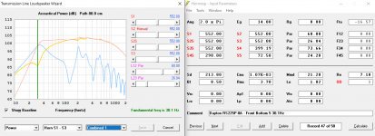
These are the Hornresp files for the two designs I posted above; with the Dayton Audio RS225P-8A woofer.
Neil,
The stuffing in zones 1 and 3 is much denser in your ported design that in your previous designs. That (and the changes in dimensions) are the reason for the differences you are seeing between the designs. Stuff your old design like that, reduce its volume and cut the final section area to 42 instead of 90 and it'll start looking a lot like your ported MLTL design.
Eric
Right - that makes sense to me. It certainly does seem like the F3 (which I was calling the "knee") as low as possible - and to have the flattest response possible down to that point. I will continue to develop the MLTL version, as you have found - it has more potential.
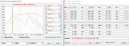
I did additional work on both designs, but the terminus opening is the better design. The fundamental frequency is now about 30Hz - which is amazing. The cabinets I built were about 36Hz, and they have better and deeper bass, than anything I have heard in my life.
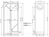
It is now a bit taller and a bit deeper front to back, than before. And I added a 4" radius at the beginning of the last segment, as this improves the extension and response. I am allowing for 2" thick eggcrate foam (which is a minimum 1" thick, and the dimples extend up to 2") to damp out more of the higher frequencies from emitting from the terminus opening.
It is now a bit taller and a bit deeper front to back, than before. And I added a 4" radius at the beginning of the last segment, as this improves the extension and response. I am allowing for 2" thick eggcrate foam (which is a minimum 1" thick, and the dimples extend up to 2") to damp out more of the higher frequencies from emitting from the terminus opening.
Attachments

Last edited:
Neil,
The simmed response looks good, but here are a few questions, comments:
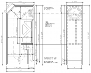
1. How are you making that 4 inch radius? It's not clear to me from the drawing.
2. The model assumes a linearly varying area in the tapered sections. But I don't think your final segment is tapers that way. So I wonder if the sim will be less accurate due to that.
3. How are you figuring how much volume the egg crate foam takes up? It's open cell right? It seems like you are assuming that the area "blocked" by the foam is not part of the port area. I have not used egg crate foam and don't know how open it is, but I'm wondering if your effective port opening might actually be closer to 2-13/16" tall vs. 1-1/4" tall.
4. Why did you decide to add the egg crate foam? It seems to me the the stuffing already there should damp the high frequencies. Why add the uncertainties and modelling ambiguities that adding the egg crate foam creates?
This is not meant to be criticism. For all I know it will work out just like you sim. But for me it's not as clear that your design in this case is as correctly represented in the Hornsrep sim as for your previous designs and corresponding sims.
Eric
The simmed response looks good, but here are a few questions, comments:
1. How are you making that 4 inch radius? It's not clear to me from the drawing.
2. The model assumes a linearly varying area in the tapered sections. But I don't think your final segment is tapers that way. So I wonder if the sim will be less accurate due to that.
3. How are you figuring how much volume the egg crate foam takes up? It's open cell right? It seems like you are assuming that the area "blocked" by the foam is not part of the port area. I have not used egg crate foam and don't know how open it is, but I'm wondering if your effective port opening might actually be closer to 2-13/16" tall vs. 1-1/4" tall.
4. Why did you decide to add the egg crate foam? It seems to me the the stuffing already there should damp the high frequencies. Why add the uncertainties and modelling ambiguities that adding the egg crate foam creates?
This is not meant to be criticism. For all I know it will work out just like you sim. But for me it's not as clear that your design in this case is as correctly represented in the Hornsrep sim as for your previous designs and corresponding sims.
Eric
Hi Eric,
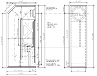
The pieces that make up the radius area would be cut square, making a stair-stepped form; which I would then smooth out into the radius with a belt sander, and an 80 grit belt. I actually made a little more tweaking to this, and ended up with a 5" radius. I have drawn these in with lighter dashed lines.
My understanding is that the air behaves relatively close to the same, whether the taper is linear or not. Partly because the taper is happening at a bend in the cabinet - which is not part of the model, either. The model is of a round space, and the cabinet is various rectangles - and the model is straight, but the cabinet is folded; but the model still applies. The model has some stepping and some tapering, and based on what I have seen, Hornresp does far better than seems possible.
On the eggcrate foam, I assumed that the "solid" 1" base is shortening the L34 segment. For the area of S4S and S5, I am counting to the midpoint of the bumps - so 1 1/2" from the bottom - because the top half of the bumps are close to equal to the dimples.
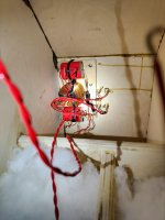
On the speakers that I built, I weighed the polyfill for the first an second sections, so it is pretty accurate based on the Hornresp model. When I measured the output of the terminus opening, it had a lot of output all the way up to 700-900Hz. Remember I am crossing the woofer with a 4th order Linkwitz Riley slope starting at 440Hz; which is considerably lower than what most 2-way woofers have. The higher frequencies were 15-20dB down from the woofer directly, but after I added (1 1/2") eggcrate foam, it audibly changed the higher frequency output from the opening.
On the speakers I have built, the terminus is 3 1/2" high, and I saw from these later models, that having a narrower opening extends the lowest bass, so constricting that earlier design is a helpful thing. For this update, since I want it to have the 1 1/4" high opening, I need to account for the foam to be in there. I am now using 2" to get as much high frequency attenuation as possible.
And since the eggcrate foam will turn up the back about 6", I am counting this as the taper in the later model, that I will include in this post. The bottom response is a touch flatter, and it keeps the 30.1Hz fundamental frequency.
The pieces that make up the radius area would be cut square, making a stair-stepped form; which I would then smooth out into the radius with a belt sander, and an 80 grit belt. I actually made a little more tweaking to this, and ended up with a 5" radius. I have drawn these in with lighter dashed lines.
My understanding is that the air behaves relatively close to the same, whether the taper is linear or not. Partly because the taper is happening at a bend in the cabinet - which is not part of the model, either. The model is of a round space, and the cabinet is various rectangles - and the model is straight, but the cabinet is folded; but the model still applies. The model has some stepping and some tapering, and based on what I have seen, Hornresp does far better than seems possible.
On the eggcrate foam, I assumed that the "solid" 1" base is shortening the L34 segment. For the area of S4S and S5, I am counting to the midpoint of the bumps - so 1 1/2" from the bottom - because the top half of the bumps are close to equal to the dimples.
On the speakers that I built, I weighed the polyfill for the first an second sections, so it is pretty accurate based on the Hornresp model. When I measured the output of the terminus opening, it had a lot of output all the way up to 700-900Hz. Remember I am crossing the woofer with a 4th order Linkwitz Riley slope starting at 440Hz; which is considerably lower than what most 2-way woofers have. The higher frequencies were 15-20dB down from the woofer directly, but after I added (1 1/2") eggcrate foam, it audibly changed the higher frequency output from the opening.
On the speakers I have built, the terminus is 3 1/2" high, and I saw from these later models, that having a narrower opening extends the lowest bass, so constricting that earlier design is a helpful thing. For this update, since I want it to have the 1 1/4" high opening, I need to account for the foam to be in there. I am now using 2" to get as much high frequency attenuation as possible.
And since the eggcrate foam will turn up the back about 6", I am counting this as the taper in the later model, that I will include in this post. The bottom response is a touch flatter, and it keeps the 30.1Hz fundamental frequency.
Attachments
Neil,
Ok, I see what you are doing with the radius. Your drawing showing the stepped pieces (before sanding) makes that much clearer. But I do wonder if you are not making unnecessary work for yourself. I tried a straight opening of 150 and got virtually identical results.
Mostly, I wonder if your assumption that the foam will act like it takes up 1-1/2" worth of space is a good one or not. I understand that the bumps and the dimples "average out". But it seems to me that your assumption is that the foam will act (in terms of cross sectional area) as if it is a solid, non-porous material. As I said before, I don't know for sure what your egg crate foam is really like, but isn't it substantially open? If so, then I'm thinking your S4S and S5 might be as much as 1.5 x 9 inches larger than you are modelling them as now. I tried it with the larger dimensions and the fundamental shifted up to about 34 Hz from 30Hz. Probably, the true "effective" area is somewhere between those extremes.
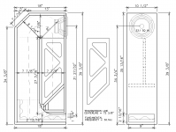
Concerning your brace. A very, very minor point, but I think it would be a bit stiffer if you made the struts to be the mirror image of their current arrangement. That is, so they meet on the left edge of the brace instead of the right side.
Eric
Ok, I see what you are doing with the radius. Your drawing showing the stepped pieces (before sanding) makes that much clearer. But I do wonder if you are not making unnecessary work for yourself. I tried a straight opening of 150 and got virtually identical results.
Mostly, I wonder if your assumption that the foam will act like it takes up 1-1/2" worth of space is a good one or not. I understand that the bumps and the dimples "average out". But it seems to me that your assumption is that the foam will act (in terms of cross sectional area) as if it is a solid, non-porous material. As I said before, I don't know for sure what your egg crate foam is really like, but isn't it substantially open? If so, then I'm thinking your S4S and S5 might be as much as 1.5 x 9 inches larger than you are modelling them as now. I tried it with the larger dimensions and the fundamental shifted up to about 34 Hz from 30Hz. Probably, the true "effective" area is somewhere between those extremes.
Concerning your brace. A very, very minor point, but I think it would be a bit stiffer if you made the struts to be the mirror image of their current arrangement. That is, so they meet on the left edge of the brace instead of the right side.
Eric
Eric, thanks again for your thoughts and comments. The effects of the radius; effectively tapering the 3rd and the 4th segments into each other, is somewhat subtle, but it lifts the response down to the F3 knee, to be a bit flatter, which is a good thing. I am hoping to wring out the most performance possible - this design is larger than the one I built, and as long as I am putting in the effort, it is worth chasing the last few hertz and decibels.
If anything, I think the foam will not act as a "stop" to the length of L34, and actually allow the resonances to be a touch better than the model shows. And as the air flows by the foam (after it has turned in to the last segment), since the foam is far higher resistance to air flow (vs the open channel), it will act like the segment is narrower there.
I can always try it without the eggcrate foam, or with 1 1/2" thick, or with the 2". This is reversible. I know that I need to damp down the high frequencies coming out of the opening, from the pair I built. So, I would rather have the greater area built into the plywood, and be able to add the foam if needed - which I am quite sure is better.
If the 'V' of the struts were mirrored, they would be bracing the upper and lower corners of the front rib, leaving a long span for the rib in the middle. It would be bracing 2 points of the front baffle, rather than 3 points. And the angled baffle is also already bracing the lower point, so having the strut there is not as useful.
Of course, I still have to see if I can cut all the pieces from a sheet 5'x5' Baltic birch plywood. If they are too big, then I will have to shrink it in one direction or another, to keep as much performance as possible. The plywood is not expensive (about $75 each with tax) but I'd like to not have to buy a third sheet just to get all the pieces I need.
Neil,
No doubt making the port too large is easier to fix later than making it too small!
Have you tried SpicyTL yet? I presume you are following that thread in the Subwoofer section. I have not had the energy to learn another model quite yet. It seems Slocum is a big fan of foam for damping of TLs and Spicy can model a foam lined TL, whereas HR cannot (AFAIK). Might be worth trying Spicy TL too for your design.
Eric
Hi Eric,
No I haven't tried SpicyTL, yet.
Open cell foam has interesting acoustic properties - if you think of foam on the walls of a room, and think about low frequency standing waves - the air in the foam cells is going to pass the pressure through to the wall, and only slow it down a tiny bit. But high frequency wave lengths are going to get slowed and damped and diffused, to a much greater extent.
And if you take an air blower and blow air parallel to the dimpled side of the eggcrate foam - not much air will divert through the back of the foam, because the resistance to flow is fairly high. If you were to blow air perpendicularly through the foam, it would slow it down a lot.
The higher the velocity the air moves, the more resistance the foam will have. If the radiator grill on a car has a lot of small holes, as the speed increases, the holes will have more and more resistance; and at some higher speed, they will effectively be closed.
I am not thinking of the speed if sound, which is essentially constant at any give temperature (and pressure) - but rather to the speed of the beats per second of the frequency of the sound. Sound is a pressure wave followed in space by a rarification. This is a push/pull on the air.
Sound acts on the air asymmetrically - the push is shaped by the speed of the object that is making the sound. But the shape of the lowered pressure part of the wave, is limited by the atmospheric pressure, to pus air back into the lower pressure zone.
I received an email about using this methodology for a full range speaker.
I'd argue that this methodology won't work well for a full range design, unless you use stuffing.
Basically, tapped horns and transmission lines will always have a notch in their response if they have no stuffing. Because there's always going to be a frequency when the output from the cone and the output from the back of the cone is out-of-phase.
You can minimize this by:
- Offsetting the woofer from the end of the TL (as this thread describes)
- Tapering the line (as this thread describes)
- If the end of the line is physically distant from the woofer cone, that can help. For instance, 150Hz is 2.27 meters long. If your hornresp prediction shows that there's a dip at 150Hz, you can reduce the depth of the dip by moving the exit of the transmission line or tapped horn to 0.57M from the woofer, or farther. Basically the additional distance will minimize the interference between the front and the back of the cone. You can simulate this in Hornresp: basically you design the speaker, and once you know where the dip is, move the woofer more than 1/4 wavelength from the exit of the TL or TH and you'll see an improvement in the dip that's inherent to designs like this.
Patrick,
We have put FRs into a zillion TLs. Many with minimal damping. It is little different than dealing with a woofer/midwoofer.
IIRC from the start of the thread, the “improved TL alignment” was not something new at the tome, the same tricks predate this thread — Patricjk has outlined 3 of these.
dave
We have put FRs into a zillion TLs. Many with minimal damping. It is little different than dealing with a woofer/midwoofer.
IIRC from the start of the thread, the “improved TL alignment” was not something new at the tome, the same tricks predate this thread — Patricjk has outlined 3 of these.
dave
I have started working on the mass loaded transmission line speakers that will use the Radio Shack made Linaeum tweeter - the 1.5" high one. I am trialing the crossover using the speakers I already built, and so far, so good! Since these are 3dB more sensitive than the woofers I will be using, I lowered them 3dB in the miniDSP. It sounds great WITHOUT doing anything to match the levels of the driver!
I started with the crossover set at 1800Hz - 12dB/octave Linkwitz Riley on the tweeter, and 24dB on the woofer. I listened, and then dropped the frequency by 100Hz and then listened a couple of times - I have changed the woofer slope to 12dB and at this point I have settled on 1250Hz for the woofer and 1300Hz for the tweeter - the wonderful ease and clarity of the Linaeum tweeters is amazing.
The LX5 Radio Shack speakers are set to about 2kHz with only 6dB/octave. So, I am not pushing the tweeter as low as it was in the factory speaker. Stock is 12dB down at 500Hz, and I have it 12dB down at 650Hz. So, I may see if it sounds better a bit lower.
The other good thing that happens by sloping the woofer off at 1250Hz - is the wavelength is ~10.8" and since that is longer than the 8" woofer cone, it maintains wider dispersion from the woofer.
So, if the 8ohm woofer is similar, then designing a simple 12dB/octave crossover may be fairly straightforward. I am going to simplify the cutting of the cabinet panels, by using biscuits.
I have "maxed" out the cabinet for the lowest F3 I can get. I am as happy as I can be, with the sound of these speakers - and the Linaeum tweeters are still my favorite tweeters. They have an effortless ease and clarity without getting harsh, ever.
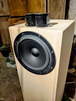
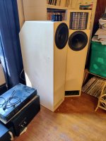
I have built a second pair of MLTL speakers, using the SB Acoustics SB23NRXS45-4 8" woofer. They use a Linaeum ET-8 (I will be building more with the ET-6A) dipole tweeter, made by Radio Shack. They sound fantastic, if I say so myself!
In the first photo, the second design is on the left, and the first one I did is on the right.
In the first photo, the second design is on the left, and the first one I did is on the right.
Attachments
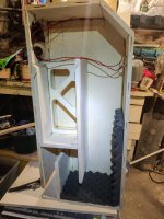
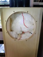
Looking great! Do you have a picture, or could you describe how you did the filling/damping of the cabinets?
I am actually going to be experimenting with more poly-fil, and then maybe with low density foam. So far, I put the ~1oz (modeled in Hornresp) into the closed end - and it just sits on the bottom; no matter how much it is fluffed up. The 2nd segment right behind the woofer has ~9oz, and I have routed the wires so they support this fairly well.
I just modeled bumping the total up to ~21oz, evenly distributed, so 14oz goes in the 1st segment (closed end) and 7oz behind the woofer. I think that this is feasible with the poly-fil I have - I can push it through the web openings in the brace for some support.
Today is also when the crossover parts are due to arrive!
Just wondering, instead of that "S"-curve at the end of the terminus, would it be possible to make a 180 degree fold and make it shoot out the back? That would probably help a little bit if there is some midrange leak through the port. It would in my opinion also look better. 😀
Anyway, just a thought 🙂
Anyway, just a thought 🙂
You know, I could try modeling that. It would shorten the 3rd segment, and change the 4th, as well. It might lift the lowest frequencies a bit more, due to the terminus opening being closer to the wall behind the speakers.
I will be doing more measurements, now that I have the analog crossovers (nearly) done. I think that the higher frequencies are damped more than the Hornresp model shows, because of the eggcrate foam, and because the S curve is going to exclude these frequencies. The Hornresp model is straight, remember.
Personally, I like the look of the terminus opening on the front, but if it works better on the back, then great! I am also planning on angling the bottom of the closed end 15-22.5 degrees; keeping the centerline length - this should broaden the resonance and reduce any standing waves. This could work with either the front, or rear location of the opening.
On the poly-fil - I started with what I had in the Hornresp model - ~1oz in the 1st (closed end) segment, and ~9oz right behind the woofer. I then modeled it with a total of ~21oz in total in those 2 segments. This lowered the F3 to 26.8Hz (from 28Hz) and sloped the shelf below ~90-100Hz down a bit more, which is fine, because the room lift at 30-45Hz is fairly significant - maybe 4-5dB, so a 1-2dB drop is actually a good thing.
But I used up what poly-fil I have by adding ~5.5oz to the 1st segment. I will probably get more poly-fil, and bump it up to the 21oz, when I add the bypass caps on the tweeter.
Attachments

Last edited:
- Home
- Loudspeakers
- Full Range
- An Improved Transmission Line Alignment