I should have said the vertical off axis measurements were taken about 1 meter away from the speaker, on the listening axis; and the 4" height changes were on that same vertical plane. So, as they get farther up or down they are a bit farther away from the speaker.
I was wondering how it is that over a 64" range of height, that the same frequency could be so sharply canceled out? Actually, the measurements at the higher part of that - have a much broader dip.
Oh, I used 1/12th octave smoothing on all the responses. The unsmoothed graphs have a very sharp point at the bottom, and they are another ~20dB lower ...
I considered a standing wave between the floor and the ceiling - the center of the woofer is 31.5" from the floor, and 70.25" from the ceiling. If this is something inside the cabinet, I will look for dimensions that are some factor of 127.9" / 10.66'
The room is 15'-10 1/4" x 12'-4 1/2" with 8'-5 3/4" ceiling - though there is a large opening on the 15'-10 1/4" side wall. The front of the speakers are 13'-10 1/2" from the wall behind the listening position. So about 2' out from the wall behind the speakers.
Last edited:
On the nearfield measurements, the two traces that touch the 85dB line are the most important - they are the nearfield of the center of the woofer (red) and the center of the opening (cyan).
These do not show a dip at 106Hz at all. But they both dip at 134Hz - the opening much more so than the woofer. They both also dip at about 38Hz and at about 60Hz.
The cool thing is the speaker is essentially flat to 30Hz, and is about 8dB down at 20Hz. Please note that I have added a 1.5" thick eggcrate foam (it is 3/4" thick at the thinnest bits in the dimples) to the bottom of the opening segment, so this may have lowered the fundamental frequency a bit from 36.7Hz?
I am not sure how to do an impedance plot, in REW?
Most of the polyfill damping is in the segment right behind the woofer, and a small portion is in the closed end. The total weight of polyfill is about 0.2kg. I added a 2' long piece of 1.5" thick eggcrate foam in the very bottom, filling the 8.5" width. Since the inside front to back dimension is 15.25", it turns up the corner at the back panel by about 9". The eggcrate foam is 0.75" thick at a minimum.
Most of the polyfill damping is in the segment right behind the woofer, and a small portion is in the closed end. The total weight of polyfill is about 0.2kg. I added a 2' long piece of 1.5" thick eggcrate foam in the very bottom, filling the 8.5" width. Since the inside front to back dimension is 15.25", it turns up the corner at the back panel by about 9". The eggcrate foam is 0.75" thick at a minimum.
Last edited:
For an impedance measurement you need a soundcard with stereo IN and a single precision resistor (I use a 47 ohm 0.1% 0.5W, but 1% is also ok) Look up the help in REW It is very easy and precise.
It will be revealing most of your problems.
It will be revealing most of your problems.
Okay, thank you for clarifying.
I recently got a Dayton Audio DATS V3 - can I use that with the woofer, to measure impedance?
I recently got a Dayton Audio DATS V3 - can I use that with the woofer, to measure impedance?
It should give you a nice curve, but i wouldn’t use the T/S derived from that curve (it does not directly measure the imporatnt parameters (according to the author).
With an impeance curve the bumps above the primary impedance are whayt you are looking for (you want to minimize them).
dave
With an impeance curve the bumps above the primary impedance are whayt you are looking for (you want to minimize them).
dave
Any method of producing a plot will show you the shape you're interested in. It's a matter of connecting to the terminals instead of a microphone and using some source resistance (that's the oversimplified version anyway).can I use that
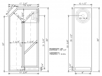
Here's the CAD drawing - the closed end is significantly shorter than before. The angled stop panel should prevent some standing waves.
Neil,
Hmm. What exactly is it that shortening the closed end does for you? It looks to me like you are wasting a lot of good volume, and you could get similar response in a smaller cabinet if you eliminate the angled member in the closed end. I think the way to deal with standing waves is with stuffing, and what you have in there already would probably be plenty, it seems to me.
Eric
By shortening the closed end, the response gets considerably better - the bumps above 200Hz that I thought were permanent - flatten out by shortening it. The angle at the end just is there to break up standing waves, without changing the tuning.
You're right that the void is a unused volume, but adding it back in means the response gets thrown off. I am considering trying to lengthen the L45 with that void, and see what that does.
But these three models / designs are the flattest and smoothest responses, with far lower fundamental frequencies, I have seen, so I am not going to sweat a bit of "wasted space".
Yes we are interested only in the fundamental TML frequency, the 3rd, 5th, ... have to be suppressed as much as possible.
The stub below the driver has the right length and will prevent the 3rd Eigenfrequency.
But if the box works as a vented box with 40Hz resonance what happens?
the vent shifts the phase and the air doesn't go thru the vent but builds up the pressure like in a closed box. It starts flowing only delayed when the box pressure has already passed the maximum.
Now at 44Hz your TML fundamental is blocked and does not develop. Only the undesired harmonics.
So you got the worst of both worlds.
By shortening the closed end, the response gets considerably better - the bumps above 200Hz that I thought were permanent - flatten out by shortening it...
But these three models / designs are the flattest and smoothest responses, with far lower fundamental frequencies, I have seen, so I am not going to sweat a bit of "wasted space".
Neil,
I see what you mean about the bumps above 200 Hz. I was not seeing those as big enough to worry about, but if you want flatten them entirely then shortening the first section does work.
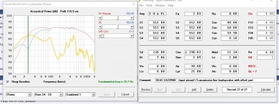
The other option would be to lower the driver (without creating the void). Then I get something like below, which is virtually as flat as the design with the void, but with the fundamental lowered to 24.6. This would put the driver between 29 and 30 from the floor (unless you put it on legs). maybe you prefer it higher?
Eric
Attachments

Hi Eric, thanks for pursuing this - I am looking for lower fundamental frequency, as well as smooth response. And I do want the woofer up as high in the cabinet as possible, to be close to the tweeter as possible. So, I will see what gets the best balance.
I have been working with a different style cabinet for someone else, here on the forum, and it also has a surprisingly low fundamental and it is very compact, too. It has a port on the back.
Can you attach the Hornresp file of this, please?
I have been working with a different style cabinet for someone else, here on the forum, and it also has a surprisingly low fundamental and it is very compact, too. It has a port on the back.
Can you attach the Hornresp file of this, please?
Last edited:
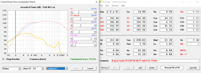
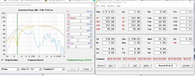
Mass Loaded Transmission Line w/ Port
I have been working in Hornresp with a new (to me) schematic design - a mass loaded transmission line with a port. The response curve looks significantly different than the previous designs, that use a terminus opening - the terminus opening designs have very flat response above the knee, and that knee is very close to the fundamental frequency, and a they slope off relatively steeply.
But the ported versions response curve is smooth but less flat, and the knee is well above the fundamental frequency, and roll off less steeply. The two other major differences: the ported design is MUCH smaller volume, and the fundamental frequency is MUCH lower.
Case in point - look at these two designs, that use the same Dayton Audio RS225P-8A woofer.
Terminus opening: 66.8 Liters / 32.3Hz
Ported: 45.67 Liters / 19.9Hz
Other differences - the terminus opening has a lot of higher frequencies coming out through it, and I would have to increase the height of the slot, and then put in a piece of eggcrate foam. The port would have to be sourced - probably a 3D printed piece.
Attachments
Last edited:
Neil,
The official name for the “port” is restricted terminus.
It acts as another LP filter allowing for less damping. Often just lined. Coupled with a Zd that kills the 1st unwanted harmonic one can yield closer to the minimum attenuation of the desired fundenmental.
The Zv can also be moved to tune things as well. Yours is at the R of your tube.
The tuning of the vent allows for a shorter physical line.
So an ML-TL is often done as a simple straight pipe.
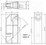
Here a quick snapshot of a planset i am working on, showing the short TL, an offset driver & vent, lined walls with low density damping righ tat the box centre to maximize absorbtion of anything moving side to side.

dave
The official name for the “port” is restricted terminus.
It acts as another LP filter allowing for less damping. Often just lined. Coupled with a Zd that kills the 1st unwanted harmonic one can yield closer to the minimum attenuation of the desired fundenmental.
The Zv can also be moved to tune things as well. Yours is at the R of your tube.
The tuning of the vent allows for a shorter physical line.
So an ML-TL is often done as a simple straight pipe.
Here a quick snapshot of a planset i am working on, showing the short TL, an offset driver & vent, lined walls with low density damping righ tat the box centre to maximize absorbtion of anything moving side to side.
dave
Attachments

At a glance, something doesn't seem right between the drawing, double port sim and your claims, so please attach an exported HR file of it.
Can you attach the Hornresp file of this, please?
Neil,
Here it is.
Eric
Attachments
Thanks, Dave - that is good to know the correct term.
These are the Hornresp files for the two designs I posted above; with the Dayton Audio RS225P-8A woofer.
These are the Hornresp files for the two designs I posted above; with the Dayton Audio RS225P-8A woofer.
Attachments
Last edited:
Neil,
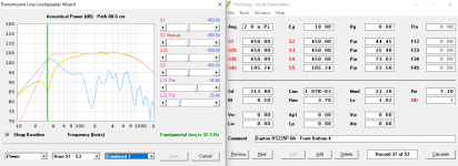
As I understand it, the only real difference between the "Horn" schematic that you've been working with until now, and the "MLTL with offset port" is that the latter version offers one more degree of freedom: It permits the port to be positioned somewhere that is not the end of the line. But otherwise they are effectively identical, and if you use "equivalent" inputs should provide the same results.
In other words, your "terminus opening" is simply a "port" that happens to be located at the end of the line.
And in your "ported" design, the port is virtually at the end of the line, so you could actually model that design reasonably well using the "horn" schematic and get virtually the same as you did with "port" schematic, as long as the inputs are equivalent.
For example, attached are two equivalent designs, based on the horn and TL schematics that yield virtually identical results.
And are you saying you are pleased with the new MLTL design? Sure, the reported fundamental is low, but if you look at the response, F3 is way higher for the new, smaller, ported design than for your original design.
Eric
Attachments
- Home
- Loudspeakers
- Full Range
- An Improved Transmission Line Alignment