@pizzacat, it sounds like the PSU and transformer are working as expected so logically it's time to check the amp boards.
Visual inspection of all solder joints and triple check that all the components match the schematic, primarily check the JFETS are right (one of each J74 and K170), that the output devices are also right (240 and 9240) and are in the correct positions.
Get one channel working before going on to the next and only connect one at any time until you get them both working. Only then should you connect them both to the PSU.
Visual inspection of all solder joints and triple check that all the components match the schematic, primarily check the JFETS are right (one of each J74 and K170), that the output devices are also right (240 and 9240) and are in the correct positions.
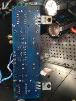
I checked all components on both amp boards again hoping I would find the problem, but I found no parts misplaced. Both the boards have the p and n channels in the right places and all resistors match the schematic.
I need to flip the boards over and check for cold solder joints, but it'll have to be another night. Also, did I mention I already connected the amp boards and got them successfully biased? The amp sounds pretty good minus the humming, and I've been listening to it for a few weeks just can't solve this hum.
Attachments


Ok that's great to hear ... I watched the youtube vid and can't say I hear anything immediately horrible but do hear a bit of transformer hum. I noticed you don't have the transformer bolted down, is it fastened some way?
If you don't have speakers connected do you still hear it or is the hum coming through the speakers?
Download the app 'Spectroid' to you phone and see what frequency the noise is predominantly at (60Hz, 120Hz, etc).
If you don't have speakers connected do you still hear it or is the hum coming through the speakers?
Download the app 'Spectroid' to you phone and see what frequency the noise is predominantly at (60Hz, 120Hz, etc).
Thanks twitchie. I won't worry about continuity between output and GND.
But is there any way to figure out what components might be fried or causing the short that is making the dim bulb stay lit without desoldering everything from the board and running them through one of those cheap component testers?
Both Mosfets measure about the same to the washer/chassis ground with about 160 ohms on the outer pins and 49 ohms on the center pin. None of the resistors seem to be fried and as best as I can tell they measure about right.
Paul,
A shot in the dark but did you set P1 and P2 to minimal value before powering up?
Referencing the schematics on page 2 here: https://firstwatt.com/pdf/art_f5_turbo.pdf
with amp power off, please confirm that the measured resistances across R5 and R6
are low (a few ohms at most). If they are not, please adjust P1 and P2 until they are.
Hi Dennis,
I did set the P1 and P2 to 0 ohms and the P3 to the middle before I mounted them. I can't seem to figure out how to post photos or I would include some of the board.
I did set the P1 and P2 to 0 ohms and the P3 to the middle before I mounted them. I can't seem to figure out how to post photos or I would include some of the board.
It's always delicate to hop in the middle of a troubleshooting session, but my heart skipped a beat when I think I saw what might be a miscommunication between Twitchie and PaulInWA.
Twitchie is noting that there should be continuity between Output(-) and GND. They are one and the same, but that's not how it's noted on the store boards.
I think PaulInWA is saying that there is continuity between what is marked as OUT on the amplifier board and GND.
This is where pictures and extremely clear descriptions are valuable. The store amp boards are marked OUT and GND. PaulInWA, if you have a very low resistance between these two points or between OUT and your "black" speaker post connected to GND, then you have an issue that needs to be sorted.
If I misinterpreted either person, apologies, but reading the posts I was not certain.
I hope it's up and working soon!
Hi Paul,
The potential issue with setting P1 and P2 to zero before soldering
is that depending on the orientation of the pot, the circuit will see it as either 0 ohm
(which is what you want) or 5k (which is not what you want). Direct measurement
at R5 and R6 gets around this problem.
To attach photos, instead of clicking "Post quick reply", click "Go Advanced". Then look
for the little paper clip button to add photos as attachement.
Cheers,
Dennis
If you don't have speakers connected do you still hear it or is the hum coming through the speakers?
Yes, I hear the hum coming from the trafo without speakers connected to the amp.
Have you tried it without the speaker protection board?
Yes. I just wired the primary of the trafo directly to a power cord and disconnected the speaker protection board. I still get hum from the trafo this way. Only trafo->psu->amp boards and the trafo still hums the same.
I noticed you don't have the transformer bolted down, is it fastened some way?
It was resting on top of rubber pencil erasers. I just bolted it tightly to the chassis until the crush washer compressed and it's still humming!
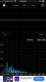
Download the app 'Spectroid' to you phone and see what frequency the noise is predominantly at (60Hz, 120Hz, etc).
I don't have android, but I found an app and it's showing a peak around 60Hz with harmonics, but its barely above the noise level in the room. I attached 2 screenshots--1st one is with amp on and 2nd is with amp powered off. There is about a 2dB difference.
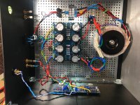
My main question is how should the PSU ground be wired? Should the ground from each rail only connect at one point at the final capacitor on each side like is shown in the F5 PSU schematic--although its ambiguous. Or should there be a ground bus with the ground side of all 10 capacitors in the PSU connected to it? And should the ground of each bridge rectifier be connected together as well?
Attachments


Itsallinmyhead - You are correct, I was talking about the speaker "Out" on the board and ground. It actually measures 30 ohms on both the board that is a problem as well as the other board I haven't installed so it isn't actually and open circuit. Pictures hopefully in my response to Dennis.
30 Ohms is fine. 😀
I don't remember you saying open circuit anywhere. If it was an open circuit, it would have showed Over Limit on your DMM, and that would indicate a problem. You said it was showing "continuity", which would usually indicate a very low resistance, but some meters "beep" at varying resistances.
Conversely, if it showed tenths of an ohm or so, that would also indicate a problem.
Hi Dennis. I attached the P1 and P2 according to the orientation shown in the V3 Build guide and I measured 0 ohms between lead 1 and 2 as marked on the potentiometer and 5000 ohms between lead 3 and either 1 or 2.
I'm not quite sure what you meant by direct measurement at R5 and R6. If I am measuring across the resistors then after a long period of rising readings both R5 and R6 stabilize at 1.06 Kohms. On the board that isn't installed and doesn't have mosfets attached those readings are 1.1K.
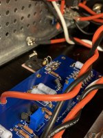
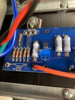
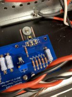
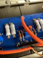
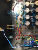
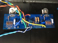
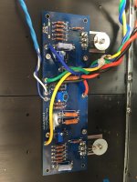
I am hopefully attaching pictures of my build.
I'm not quite sure what you meant by direct measurement at R5 and R6. If I am measuring across the resistors then after a long period of rising readings both R5 and R6 stabilize at 1.06 Kohms. On the board that isn't installed and doesn't have mosfets attached those readings are 1.1K.
I am hopefully attaching pictures of my build.
Attachments
30 Ohms is fine. 😀
I don't remember you saying open circuit anywhere. If it was an open circuit, it would have showed Over Limit on your DMM, and that would indicate a problem. You said it was showing "continuity", which would usually indicate a very low resistance, but some meters "beep" at varying resistances.
Conversely, if it showed tenths of an ohm or so, that would also indicate a problem.
I guess my multimeter has a different idea of continuity/short than I do because it beeped for continuous circuit but using the better multimeter it gave the 30 Ohm reading.
I'm guessing there is a short circuit somewhere because isn't that the reason the Dim Bulb tester never dims and the PSU LEDs never light up? Although thinking about it, if there is a short circuit in the amp board why would that stop the LEDs on the PSU from lighting? I really wish I had paid a little more attention to the circuit design class I took as a teenager LOL.
Understand completely.
Backing up a bit to answer one piece for clarity, what Dennis means is to set your DMM to resistance. Place the leads at either side aka "across" R5 and turn P1 until it reads the lowest resistance.
Then do the same for R6 / P2.
In addition, even though they may not be touching the heatsinks, those leads on the bottom of your board look long. While you have it up, I'd trim them off.
What ItsAllInMyHead said. 🙂
Paul, your measurement of ~1K across R5 and R6 would likely result in the output mosfets turning on quite hard and pulling a lot of current.
Paul, your measurement of ~1K across R5 and R6 would likely result in the output mosfets turning on quite hard and pulling a lot of current.
Understand completely.
Backing up a bit to answer one piece for clarity, what Dennis means is to set your DMM to resistance. Place the leads at either side aka "across" R5 and turn P1 until it reads the lowest resistance.
Then do the same for R6 / P2.
In addition, even though they may not be touching the heatsinks, those leads on the bottom of your board look long. While you have it up, I'd trim them off.
OK. Thanks to you and Dennis. Measuring across R5 and R6 which initially measured 1.06 kOhms I adjusted the P1 and P2 potentiometers so that that resistance is now 0.2 ohms. So I guess that means I had the pots set all the way in the wrong direction despite my best efforts to have measured correctly preinstallation?
I haven't tried turning the amp on after resetting the P1 and P2. I thought I should ask first if there is anything else I should be concerned about.
And I was aware of the long lead length on the underside of the board but everything clears the chassis by at least an 1/8" or so. Voltage seems low enough that it is hard to imagine any arcing or short circuit that way.
I'd trim those leads off, since you have it off the sinks anyway. If even a whisker from your V+ or V- wiring touches the sinks...
Edited to add - LOL! You beat me to answering. Sounds like not a worry. You're good to go.
Edited to add - LOL! You beat me to answering. Sounds like not a worry. You're good to go.
I agree with ItsAllInMyHead. If the wiring looks fine then I would give it a go with the light bulb tester.
- Home
- Amplifiers
- Pass Labs
- An illustrated guide to building an F5