Without applying power, what resistance do you measure across
R5 and R6? (See post #1447: https://www.diyaudio.com/forums/pass-labs/188691-illustrated-guide-building-f5-145.html#post6341028 )
R5 and R6? (See post #1447: https://www.diyaudio.com/forums/pass-labs/188691-illustrated-guide-building-f5-145.html#post6341028 )
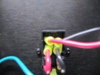
No need to remove fuses. Can you test continuity from the power cord to the back of the switch?
And test the fuses for continuity; its not always obvious that they've blown.
@Chiptech
When posting for troubleshooting over a few days, it can be tricky to keep track of things.
So far have you:
1) checked PSU for proper rails with no amp boards connected? Have you tested the full PSU inside the chassis with permanent wiring to everything including fuses etc.? I suggest this only b/c testing the PSU outside the chassis or with some other partial configuration has worked fine for me, and then I bungled the installation in one case. It led to me chasing my tail for a bit. tl;dr - have you completely ruled out the PSU back to the mains?
2) installed and mounted both amp boards to your heatsinks with nothing else connected to the amp boards and checked the continuity of each of the pins on the output devices to the heatsink with no "beeps"? No continuity at all. I ask b/c you said that your dim bulb checks looked fine until you connected one amp board. Two common causes can be: not setting the bias pots properly prior to firing it up and the amp board drawing too much current (you seem to have ruled that out); and/or a short from somewhere on the amp board to the chassis / heatsink. Tears or pinholes in Keratherm (or other material) have caused issues in the past for other builders.
Hopefully it is something simple like that. If not, it's nice to rule it out first.
Looking forward to seeing some pics.
@Chiptech
When posting for troubleshooting over a few days, it can be tricky to keep track of things.
So far have you:
1) checked PSU for proper rails with no amp boards connected? Have you tested the full PSU inside the chassis with permanent wiring to everything including fuses etc.? I suggest this only b/c testing the PSU outside the chassis or with some other partial configuration has worked fine for me, and then I bungled the installation in one case. It led to me chasing my tail for a bit. tl;dr - have you completely ruled out the PSU back to the mains?
2) installed and mounted both amp boards to your heatsinks with nothing else connected to the amp boards and checked the continuity of each of the pins on the output devices to the heatsink with no "beeps"? No continuity at all. I ask b/c you said that your dim bulb checks looked fine until you connected one amp board. Two common causes can be: not setting the bias pots properly prior to firing it up and the amp board drawing too much current (you seem to have ruled that out); and/or a short from somewhere on the amp board to the chassis / heatsink. Tears or pinholes in Keratherm (or other material) have caused issues in the past for other builders.
Hopefully it is something simple like that. If not, it's nice to rule it out first.
Looking forward to seeing some pics.
One thing i've started to do with any amplifier builds is to separate things and build them as separate components as you've said above. The one thing I've to add to what you said is that before I connect the amplifier boards/section to the PS is to use my DC bench supply (which has current and voltage limiting). This is a known quantity and works, so it is a solid way to test the boards in an isolated way without worrying about the supply or chassis build. Once both are determined to work separately, then I connect the amp boards (one at a time), etc...
+1 agreed. 🙂
The primary reason I did not include that for this specific case is the uncertainly re: Chiptech's availability of a supply (or two) that would provide both positive and negative rails and the potential complexity of setting them up for current limiting and proper configuration for both rails. I maaaaaaaaay know someone that almost fried an output stage by hooking up lab supplies as two positive rails.

The primary reason I did not include that for this specific case is the uncertainly re: Chiptech's availability of a supply (or two) that would provide both positive and negative rails and the potential complexity of setting them up for current limiting and proper configuration for both rails. I maaaaaaaaay know someone that almost fried an output stage by hooking up lab supplies as two positive rails.
And test the fuses for continuity; its not always obvious that they've blown.
Fuse is good.
First off, thanks for the assistance. While I have built many audio components from kits, the F5 has always been my stretch project. I've learned a lot so far.
Per an earlier question, the fuse is good.
Per an earlier question, the fuse is good.
@Chiptech
When posting for troubleshooting over a few days, it can be tricky to keep track of things.
So far have you:
1) checked PSU for proper rails with no amp boards connected?
No I have not. I need some direction here. I've searched for measuring PSU rails without success. How do I proceed?
Have you tested the full PSU inside the chassis with permanent wiring to everything including fuses etc.?
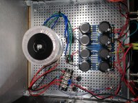
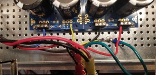
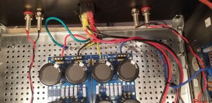
All my results as reported are with the amp as built. See photos.
I suggest this only b/c testing the PSU outside the chassis or with some other partial configuration has worked fine for me, and then I bungled the installation in one case. It led to me chasing my tail for a bit.
Have you completely ruled out the PSU back to the mains?
So no I have not ruled out the PSU back to the mains. Sounds like a good place to start.
see photos

Chiptech,
A recap:
You had previously tested the power supply alone with the dim bulb tester and it passed.
You then connected one channel to the power supply and the bulb stayed bright - a problem.
Dennis asked you to check resistance at R5 and R6 which should be close to zero, and you measured 0.761R and 0.659R, which is good.
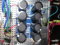
Looking at your pictures, you have red wires for both V+ and V-. Ideally you should have one colour for V+ and another for V- so that identification is easy and mixups are less likely.
To test the power supply without any boards connected, use your voltmeter and measure DC Volts between Ground and V+ and between Ground and V-. You should get somewhere around 25V or so.
If that is good, connect one board to the power supply and take pictures of the wiring and also take pictures of the amplifier board so that it can be examined for possible errors. Make sure you identify V+ and V- wires from the power supply. If both are red, wrap some coloured tape around the end of V- to differentiate it from V+.
A recap:
You had previously tested the power supply alone with the dim bulb tester and it passed.
You then connected one channel to the power supply and the bulb stayed bright - a problem.
Dennis asked you to check resistance at R5 and R6 which should be close to zero, and you measured 0.761R and 0.659R, which is good.
Looking at your pictures, you have red wires for both V+ and V-. Ideally you should have one colour for V+ and another for V- so that identification is easy and mixups are less likely.
To test the power supply without any boards connected, use your voltmeter and measure DC Volts between Ground and V+ and between Ground and V-. You should get somewhere around 25V or so.
If that is good, connect one board to the power supply and take pictures of the wiring and also take pictures of the amplifier board so that it can be examined for possible errors. Make sure you identify V+ and V- wires from the power supply. If both are red, wrap some coloured tape around the end of V- to differentiate it from V+.
^^ do everything Ben said.
( Using the same color wire for both V+ and V- is a pretty dismal idea as he hinted at, I’d make a run to the hardware store and get something different for V-. )
( Using the same color wire for both V+ and V- is a pretty dismal idea as he hinted at, I’d make a run to the hardware store and get something different for V-. )
@Chiptech
I gotta say...I admire the methodical way you're going about this project. Saves on burnt parts!
I gotta say...I admire the methodical way you're going about this project. Saves on burnt parts!
Ok. I get a reading of 24.33 from each PSU channel.
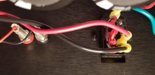
I have attached new photos. Blue cable is the V- connection.
I appreciate help in debugging this.
I have attached new photos. Blue cable is the V- connection.
I appreciate help in debugging this.
Attachments
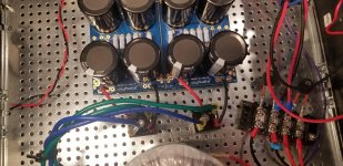

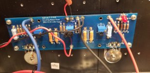

Your power supply voltage is good. Your wiring to the amplifier board looks good.
Looking at the P channel Mosfet (right side of board), the thermistor wire may possibly be contacting the washer/screw. Make sure that only the body of the thermistor is in contact.
Once that is done you are ready for power up with the dim bulb tester. Having two meters for the biasing is best, with one meter set to DC Volts on the speaker out and the other meter across R7, also set to DV Volts.
If all is good, the dim bulb tester should dim after intially glowing bright.
The voltage across R7 should be very low (much less than 1V).
If good, then biasing is next.
Edit 2:
I can't tell from your picture but are the thermistors in the board thermistor holes? Looking at the picture it looked like they are on the Mosfet pins, but that is probably a illusion.
Last edited:
Hi Ben - The thermistors have their own pads below the MOSFETs. FWIW, they look correct to me. P channel side goes to R21 / Source. N channel goes to R22 / Source.
Edit - Unless the photo is showing the legs directly shorted to the MOSFET pins...
Edit - Unless the photo is showing the legs directly shorted to the MOSFET pins...
- Home
- Amplifiers
- Pass Labs
- An illustrated guide to building an F5