P3
I am just about ready to fire up my F5 boards for the first time and needed to verify that P3 is optional if you don't have the correct equipment to set it. I have zeroed out P1&2. I have not been able to locate the actual instructions for setting the Bias and Im sure its in there, if someone knows off the top of their head what the post number is, I would be grateful.
Thanks,
Bill
Omit or leave with the pot centered, either is fine.
Bias procedure in this thread can be found in post #2
Bias procedure in this thread can be found in post #2
Last edited:
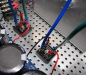
Add a zero to your note for the caps (I can see it on the can itself), and yep. Note, I did not review wiring - just parts descriptions.
Edited to add - OK... I did not see the cap across your primaries, and someone with better eyes and skills than I should review how you've got 3? thermistors (I can't tell what the lonely one is) arranged along with a full wiring review if you haven't done that. I'd recommend NOT firing that up without confirmation from a trusted source.
Edited to add - OK... I did not see the cap across your primaries, and someone with better eyes and skills than I should review how you've got 3? thermistors (I can't tell what the lonely one is) arranged along with a full wiring review if you haven't done that. I'd recommend NOT firing that up without confirmation from a trusted source.
Last edited:
thanks. one small step at a time. Very helpful to avoid plunging over the cliff. more to come.
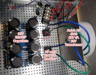
Transformer Secondaries
Ok. I have the positive from the amp board to the + on the rectifiers and black - across from the red +.
Now how do I position the transformer secondaries into the rectifiers? I have them positioned as I've seen in other photos. I've looked but haven't seen or missed any help on this issue.
Ok. I have the positive from the amp board to the + on the rectifiers and black - across from the red +.
Now how do I position the transformer secondaries into the rectifiers? I have them positioned as I've seen in other photos. I've looked but haven't seen or missed any help on this issue.
Attachments
With Antek transformers, each secondary pair are green and blue. You need to verify that the green and blue that you have grouped together are of the same secondary. To do that, disconnect the green and blue from the rectifier and check with a meter that there is continuity.
Once your power supply is complete, you should test it. For the first power-up, you should use a dim bulb tester which will limit the current if you have a mistake in the wiring that may cause a short.
Google dim bulb tester if you need more information.
Post #2 has some information on dim bulb tester.
Post #1 has the schematic for the power supply. Follow that. It shows the two secondaries connected to the two rectifiers. You need to study the schematic as it shows the wiring arrangement. The lines on the schematic represent wires and show how to connect the components. Study it and compare it to what you have wired up.
Last edited:
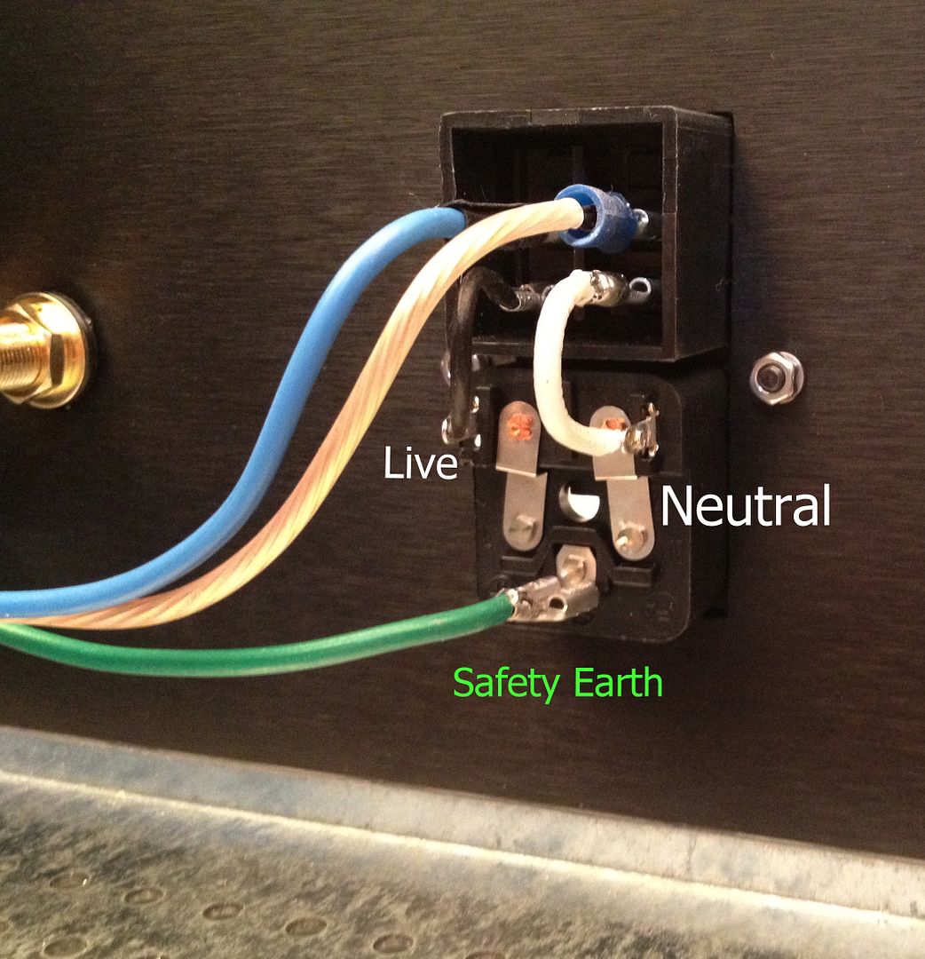
I plan to use a Schurter AC Power Entry Modules w/Fuseholder and Switch model # 4304.6090, which i think i was guided to here. Is this in fact a good PEM to use? And if so, I cannot find a wiring guide for this switch. Any help is appreciated. I havce toured the web without satisfaction.
]https://www.mouser.com/ProductDetail/Schurter/43046090?qs=%2Fha2pyFaduhp8YcymUPJozI0LvduXmLOuN1CHeRFAC0%3D[/url]
]https://www.mouser.com/ProductDetail/Schurter/43046090?qs=%2Fha2pyFaduhp8YcymUPJozI0LvduXmLOuN1CHeRFAC0%3D[/url]
Attachments
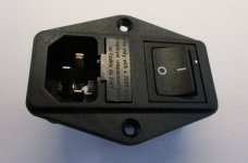
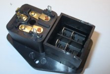
do these power entry modules come with the fuse in them? If not what type and size would you use?
These entry modules don't come with fuses. You should check your particular one
for the sizing. For example, the one Chiptech mentioned in post #1393 uses
5mm x 20mm fuses, according to the spec sheet:
https://www.mouser.ca/datasheet/2/358/typ_6765-1275662.pdf
For a standard F5 build in North American (~115VAC power), use a 2.5A slow blow fuse.
for the sizing. For example, the one Chiptech mentioned in post #1393 uses
5mm x 20mm fuses, according to the spec sheet:
https://www.mouser.ca/datasheet/2/358/typ_6765-1275662.pdf
For a standard F5 build in North American (~115VAC power), use a 2.5A slow blow fuse.
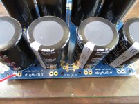
I've put together the components as shown in the photo from various BOMs i've found here. Am I on track? Do they work together?
Thanks
Looks like your cables from bridge rectifiers to power supply pcb are suspiciously thin, what gage are you using?
Bear in mind that when you turn on the amp, since the cap bank is empty, those cables need to carry a massive current, and you would want something thick enough to cope with it: eg Awg 14 or 16 as a minimum
I checked on the store and the boards are not available - only the Turbo. Does someone know if there will be back on stock fairly soon?
These entry modules don't come with fuses. You should check your particular one
for the sizing. For example, the one Chiptech mentioned in post #1393 uses
5mm x 20mm fuses, according to the spec sheet:
https://www.mouser.ca/datasheet/2/358/typ_6765-1275662.pdf
For a standard F5 build in North American (~115VAC power), use a 2.5A slow blow fuse.
Thanks Dennis
- Home
- Amplifiers
- Pass Labs
- An illustrated guide to building an F5