The loop back FFT looks good, so the Focusrite/REW setup seems good.
Turn off the REW Signal Generator and send the oscillator output to the Focusrite and see if the measurement is better today.
Turn off the REW Signal Generator and send the oscillator output to the Focusrite and see if the measurement is better today.
I did, and I get no better measurement using the Oscillator than before.Turn off the REW Signal Generator and send the oscillator output to the Focusrite and see if the measurement is better today.
I set an email to Dan at Akitika asking if he's ever had an instance of one of the Oscillators not meeting spec. Maybe he can help.
So back ~14 years ago, would the F5 measured for the article have had the Harris parts installed?The 2nd harmonic is very dependent on the gain ratios of the transistors on the positive half vs negative half.
The P ch mosfets routinely have less transconductance than the N's so some 2nd will occur. You can minimize this with device choices, for example with the old Harris devices.
At the same time, the 2nd harmonic would likely be negative phase, so you might choose to just enjoy....

From the F5 article ( https://firstwatt.com/pdf/prod_f5_man.pdf page 13):
"Comparable parts are widely available, and here I used Fairchild FQA12P20 and FQA19N20C."
You can also see them in some of the 6moons F5 review: photos
http://6moons.com/audioreviews/firstwatt7/f5_2.html
"Comparable parts are widely available, and here I used Fairchild FQA12P20 and FQA19N20C."
You can also see them in some of the 6moons F5 review: photos
http://6moons.com/audioreviews/firstwatt7/f5_2.html
LOL! I'm too slow. Also included in another article (if this is the article Kevin was referencing).
https://audioxpress.com/article/you-can-diy-the-f5-power-amplifier
Parts Selection
...The output MOSFETs are the IRF240 N channel type (Q3) and the IRD9240 P channel type (Q4). They will need a voltage rating in excess of 50V, a current rating of about 15 to 20A, and a dissipation of about 150W. Comparable parts are widely available, and here I used Fairchild FQA19N20C and FQA12P20...
Doubling up to both show the other article... and so I can share my favorite (so far) statement from the article...
"You might not want to call a quantum mechanic if your plumbing stops up." - Nelson Pass
Yes, that's the original F5 article, which is also included as part of the F5 user manual.

I have some Harris P channel parts. Is there any advantage to pairing them with N channel manufactured by Harris? Or will the IR N channel work just as well?The P ch mosfets routinely have less transconductance than the N's so some 2nd will occur. You can minimize this with device choices, for example with the old Harris devices.
I recently asked Pa the same question. He sez the N channel parts are not that different, so since I have a bunch of Vishays, he recommended I use them, in my case for a BA-3. I have Harris P’s.I have some Harris P channel parts. Is there any advantage to pairing them with N channel manufactured by Harris? Or will the IR N channel work just as well?
Regards.
Andy
BTW, I sent my Oscillator back to Dan at Akitika for testing. Should be interesting.The loop back FFT looks good, so the Focusrite/REW setup seems good.
Turn off the REW Signal Generator and send the oscillator output to the Focusrite and see if the measurement is better today.
So here's my deal...I have 100 IRFP9240's Manufactured by Harris. I have measured these parts and they are close in VGS ranging from 3.62 - 3.69V. I can get 100 IRFP240's (regular IR type) from @rhthatcher that are know to be in that same range, OR I could roll the dice on 100 IRFP240's manufactured by Harris and hope for good matches. Probably a no brainer, but what would you do?I recently asked Pa the same question. He sez the N channel parts are not that different, so since I have a bunch of Vishays, he recommended I use them, in my case for a BA-3. I have Harris P’s.
Regards.
Andy
If buying 100, I agree: no brainer. Be quick, or Pa’ll beat you to itSo here's my deal...I have 100 IRFP9240's Manufactured by Harris. I have measured these parts and they are close in VGS ranging from 3.62 - 3.69V. I can get 100 IRFP240's (regular IR type) from @rhthatcher that are know to be in that same range, OR I could roll the dice on 100 IRFP240's manufactured by Harris and hope for good matches. Probably a no brainer, but what would you do?

I you do, I’d be very interested in a few

Edit: Going for the 100 Harrises also keeps them old NOS’es within the GBC (Greedy Boy Community)

Yup, GBWA, straight outta Sea Ranch
Last edited:
Got my Oscillator back from Dan and everything tested within spec.BTW, I sent my Oscillator back to Dan at Akitika for testing. Should be interesting.
On December 3, I measured the Oscillator direct to the Focusrite and got this graph and THD measurement:The loop back FFT looks good, so the Focusrite/REW setup seems good.
Turn off the REW Signal Generator and send the oscillator output to the Focusrite and see if the measurement is better today.

Today I made the same measurement (Oscillator direct to the Focusrite) changing only the adapter feeding the Focusrite:

The adapter on the left (TRS to RCA) was used for the Dec. 3 measurement. The adapter on the right (XLR to RCA) for the measurement today.

Why the huge difference?
What Jim said.
I made my own cable with RCA on one end and XLR on the other end. The XLR has pins 1 and 3 connected to RCA ground.
I made my own cable with RCA on one end and XLR on the other end. The XLR has pins 1 and 3 connected to RCA ground.
Shorting the other input doesn’t do much.
Keeping everything the same and just switching adapters, the TRS/RCA measures 20dB less than the XLR/RCA on the fundamental.
Keeping everything the same and just switching adapters, the TRS/RCA measures 20dB less than the XLR/RCA on the fundamental.
I suppose you could move the cable to the other side of the adapter and short the unused RCA and see what happens. But in the end you now know what to do - use the XLR connector. 🙂
Shorting the other input doesn’t do much.
Keeping everything the same and just switching adapters, the TRS/RCA measures 20dB less than the XLR/RCA on the fundamental.
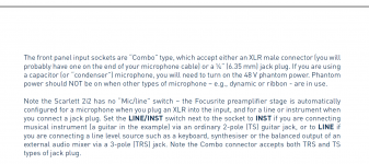
I've got an idea of what causes the differences between the two adapters. The front panel combo plug, XLR/TRS, is used as "Microphone" input when TRS is used, and "Line" input when XLR is used. Microphone having a 2K impedance and Line having 10K impedance.I suppose you could move the cable to the other side of the adapter and short the unused RCA and see what happens. But in the end you now know what to do - use the XLR connector. 🙂

Great researching. The microphone input (XLR) has the best specifications (noise and THD) and the instrument/line input (TRS) has the worst specifications.
So the XLR input is the one to use.
From the Focusrite 2i2 user guide (my 2i2 is a Gen 2):
So the XLR input is the one to use.
From the Focusrite 2i2 user guide (my 2i2 is a Gen 2):
Attachments

Last edited:
- Home
- Amplifiers
- Pass Labs
- An illustrated guide to building an F5