I have completed my F5 build and have started the Bias/offset adjustment. I have connected meters as directed. The voltage on my power supply reads 24.9 volts. On power up the meters connected to R7, R8 and the output are showing 0 volts. P1 and P2 were dialed down to close to 0 ohms before install. I started the adjustment of P1 and P2 a full turn (clock wise). After about 10 turns on each pot, none of the meters are registering any voltage. Is this normal? Does it take a lot of turns before I should be seeing a result?@bermek
Adjustments (Bias and Offset, set with P1 and P2)
This is easiest with three DMM.
Shorting the input jacks is helpful, although not strictly necessary.
Before power up, dial pots P1 and P2 to 0 ohms . DON'T adjust P3 during bias
Place one voltmeter (Set to DC volts) across the speaker output jacks - to observe DC offset
Place a voltmeter (Set to DC volts) across R7, and another across R8.
For test - slowly dial up Variac ( presuming that you have one , as man with many skills) up to full mains voltage , observing rail voltage at PSU ....... thinking about max cap voltage ( 25V as in FW ? ) , because with 0 Iq PSU is unloaded and voltage is maxed (It’s useful to have another meter for this…) If nothing is smells bad, and the magic smoke is still in the circuit - leave Variac at full mains ;
IF you don’t have a Variac, you must build a lightbulb mains lead. (with a 25W bulb)
What's important - Iq (measured as the voltage across source resistors; the Mosfet bias) must be very low , offset is irrelevant in this moment .
Now turn one pot one turn ( assuming that you have multiturn pots) then turn other pot one turn. Continue, one turn at a time on each pot until something happens.
Observe voltage across resistors and output DC offset.
Proceed one then second pot , again just one turn
Observe Iq and offset
Again one turn + one turn
Now you are probably in range when you can see which pot is pulling offset in right direction - to 0 . It will feel like one of the pots is controlling the bias on both sides of the circuit, and the other is controlling the DC offset. (That’s not what’s actually happening, but carry on…)
It’s best to increase the bias a bit, and then zero the offset. As you zero the offset you will decrease some of the bias, so it will be two steps forward and one step back. This action is normal.
As you increase the bias and zero the offset, remember to always keep the offset near zero. If you run out of turn on the pots, determine your max bias, with zero offset. (It’s useful for troubleshooting)
Proceed iteratively with pots , while you set - say - 80% of desired bias, with zero offset. Remember, full bias is 0.6V across R7 and R8, with zero offset At the speaker jacks.
Now - put lid on box and let it cook for a while - until you get thermal equilibrium on heatsinks
It's best to use wire/clips to leave those voltmeters in place ;
Open the lid , up bias to - say - 90% of desired one ,while maintaining offset
Put lid on , let it cook.
Check again.
If all is OK - move voltmeters for Bias and offset to other channel and repeat procedure.
Use it few days at 90% of desired bias , then check and set to 100%
Remember - temp. equilibrium with lid on is important.
Thanks
Well, it's back to the future. My first Pass diy amp was the F5. I have been curious about how to build a dual mono and then I hit the mother lode.
I checked the bias on the right channel and it was .35V. I couldn’t get a reading on the left channel bias.
I successfully rebiased the right channel to .59V, but so far I can’t get any bias reading or heat on the left channel and I have gotten to the full on position on the pots.
Close examination of the board doesn’t show anything burned. Testing the resistors in the board, they all give a reading so none are burned out. All four 10Ohm 3W resistors show only 29.3 ohm readings which is a bit weird. I can pull one out to test it.
Did I do some serious damage to the left channel?
Scratching my head at this point and would appreciate any thoughts….
DamonB showed the way with his F6 duo mono: (5) F6 Illustrated Build Guide | Page 226 | diyAudio #4509. So I decided to upgrade my F5 to duo mono. It was a fun build and I arrived at the day that the new duo PSU’s were both measuring 23.5 DCV.
My F5 build was in good working order before I started. But when I put it in my system with the new PSU set up, the sound was poor from both channels and the left channel heat sink didn’t warm up at all.I checked the bias on the right channel and it was .35V. I couldn’t get a reading on the left channel bias.
I successfully rebiased the right channel to .59V, but so far I can’t get any bias reading or heat on the left channel and I have gotten to the full on position on the pots.
Close examination of the board doesn’t show anything burned. Testing the resistors in the board, they all give a reading so none are burned out. All four 10Ohm 3W resistors show only 29.3 ohm readings which is a bit weird. I can pull one out to test it.
Did I do some serious damage to the left channel?
Scratching my head at this point and would appreciate any thoughts….
Attachments
Remove the mounting screws/washers and double check that you have a 9240 on Q3 and a 240 on Q4.

Might be worth checking the diode bridges wiring for the left chan PSU positive rail, and also double check the function of that rail if not allready done. It’s LED seems unlit too. I seem to remember another builder recently made a mistake there when redoing his PSU, as simple as wire termination mixup at the bridges i believe. Easy to do.Well, it's back to the future. My first Pass diy amp was the F5. I have been curious about how to build a dual mono and then I hit the mother lode.
DamonB showed the way with his F6 duo mono: (5) F6 Illustrated Build Guide | Page 226 | diyAudio #4509. So I decided to upgrade my F5 to duo mono. It was a fun build and I arrived at the day that the new duo PSU’s were both measuring 23.5 DCV.
My F5 build was in good working order before I started. But when I put it in my system with the new PSU set up, the sound was poor from both channels and the left channel heat sink didn’t warm up at all.
I checked the bias on the right channel and it was .35V. I couldn’t get a reading on the left channel bias.
I successfully rebiased the right channel to .59V, but so far I can’t get any bias reading or heat on the left channel and I have gotten to the full on position on the pots.
Close examination of the board doesn’t show anything burned. Testing the resistors in the board, they all give a reading so none are burned out. All four 10Ohm 3W resistors show only 29.3 ohm readings which is a bit weird. I can pull one out to test it.
Did I do some serious damage to the left channel?
Scratching my head at this point and would appreciate any thoughts….
A very quick test is to measure the rails to gnd at the left channel amp board. If it is a PSU issue it will show up there.
If the amp boards are untouched - completely - during the dual mono conversion, simply look to the PSU, is my advice.
Looks great btw!
Meaning +23.5V and -23.5 V on both supplies?the new duo PSU’s were both measuring 23.5 DCV.
Call me crazy but isn't there supposed to be a pot at the "P3" position. If not a pot a resistor or jumper. It has been a couple of years since I completed
my F5 but I known for a fact there is a pot on my amp boards.
my F5 but I known for a fact there is a pot on my amp boards.
Chiptech,
Please start with the basic stuff by confirming the voltages of the V+/GND/V- both on the PSU pcb and on the amp board PCB as others have suggested. Does the LED light up on the PCBs?
Take a look at the thermistor as Ben suggested.
What did you do (if anything) to the amp PCBs in the process? Did you take them off the heatsinks or just changed the PSU wiring?
Please do not pull the 100 ohm 3W resistors. 29 ohms sounds about right since there are lots of things in parallel and series. In any case, you can compare that with the working board, but right now there's no indication that is a problem.
Andynor,Might be worth checking the diode bridges wiring for the left chan PSU positive rail, and also double check the function of that rail if not allready done. It’s LED seems unlit too. I seem to remember another builder recently made a mistake there when redoing his PSU, as simple as wire termination mixup at the bridges i believe. Easy to do.
A very quick test is to measure the rails to gnd at the left channel amp board. If it is a PSU issue it will show up there.
If the amp boards are untouched - completely - during the dual mono conversion, simply look to the PSU, is my advice.
Looks great btw!
I was that guy who you helped figure out the termination mixup. That was when I ported my F5 from a 5U to a 4U case.
Today I realized I didn't have the same parallel wiring from the blocks to the PSU boards. I changed the left amp terminals to match right. I have fixed that. Not sure it would make a difference. New measurements: Right -21.95 DCV Left +23.82 DCV.
Rails to grd measure: Left-21.95 DCV Right +1.6 DCV So that is a problem.
Good thing current wasn't flowing to left amp board because the pots full on. Oops.
Misc:
1 led on the right PSU doesn't work because I wired it wrong.
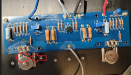
Thermistor is not shorting - doesn't touch washer.
Thanks for all the help.
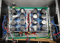
Attachments
Good job! Maybe one step closer. Have you checked the right channel gnd connection is good? Does it measure the same at the PSU board, or only at the amp board?Andynor,
I was that guy who you helped figure out the termination mixup. That was when I ported my F5 from a 5U to a 4U case.
Today I realized I didn't have the same parallel wiring from the blocks to the PSU boards. I changed the left amp terminals to match right. I have fixed that. Not sure it would make a difference. New measurements: Right -21.95 DCV Left +23.82 DCV.
Rails to grd measure: Left-21.95 DCV Right +1.6 DCV So that is a problem.
Good thing current wasn't flowing to left amp board because the pots full on. Oops.
Misc:
1 led on the right PSU doesn't work because I wired it wrong.
Thermistor is not shorting - doesn't touch washer.
Thanks for all the help.
Happy New Year, by the way 🙂
A bit confusing so please clarify - what are the V+ and V- for the left channel and what are the V+ and V- for the right channel? Are these voltages with the amplifier boards connected?......
Today I realized I didn't have the same parallel wiring from the blocks to the PSU boards. I changed the left amp terminals to match right. I have fixed that. Not sure it would make a difference. New measurements: Right -21.95 DCV Left +23.82 DCV.
Rails to grd measure: Left-21.95 DCV Right +1.6 DCV So that is a problem.
...........
It is best if you disconnect the boards from the PS boards and confirm that the PS boards are working correctly. Only then connect the amplifire boards if you are getting the correct voltages. When connecting the amplifier boards, only connect one channel and get that working before connecting the other channel.
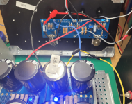
with no connections to amp boards, the PSU readings are:
Right +24.84 DCV and -24.92 DCV
Left +24.78 DCV and -24.78 DCV
Right +24.84 DCV and -24.92 DCV
Left +24.78 DCV and -24.78 DCV
Your power supplies seem to be working properly.
Connect your right channel board. Double check your wiring - V- from PS to V-, V+ from PS to V+, Ground from PS to Ground. Check that the thermistors are placed properly and not shorting. To be careful, power up with a dim bulb tester and check voltages. Are you getting equal V+ and V- at the board? Do the trim pots work for bias and offset? If yes, set bias for a low amount and remove DBT and power up and check voltages and continue bias and offset adjustments.
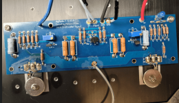
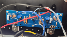
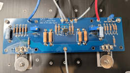
If it is not working properly, post clear focused pictures of the board, the power supply, and wires from PS board to amplifier board, and describe what you encountered.
Connect your right channel board. Double check your wiring - V- from PS to V-, V+ from PS to V+, Ground from PS to Ground. Check that the thermistors are placed properly and not shorting. To be careful, power up with a dim bulb tester and check voltages. Are you getting equal V+ and V- at the board? Do the trim pots work for bias and offset? If yes, set bias for a low amount and remove DBT and power up and check voltages and continue bias and offset adjustments.
If it is not working properly, post clear focused pictures of the board, the power supply, and wires from PS board to amplifier board, and describe what you encountered.
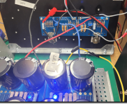
My right channel is working to spec.
The left channel is the challenge. I measure +/-24.61 DCV to the amp board.
But neither pot appears to be working.
From my own past experience, I know I'm missing some simple thing...
The left channel is the challenge. I measure +/-24.61 DCV to the amp board.
But neither pot appears to be working.
From my own past experience, I know I'm missing some simple thing...
Attachments
So the board was working properly before the PS change. Now the board doesn't work when connected to the new PS, and the board is getting correct voltages from the PS.
Please measure the voltages across the following resistors: R3, R4, R5, R6, R7, R8, R17, R18
Please measure the voltages across the following resistors: R3, R4, R5, R6, R7, R8, R17, R18
You mentioned pots being turned all the way up. You may have blown something at first startup. Ben’s measurement suggestions should give good indications. Your pots may be ok, you active devices or other stuff may not.My right channel is working to spec.
The left channel is the challenge. I measure +/-24.61 DCV to the amp board.
But neither pot appears to be working.
From my own past experience, I know I'm missing some simple thing...
That was why I mentioned powering up with a DBT first (post #2215). However things could have been toasted on the very first power-up.
It's always a good idea to use a DBT for the very first power-up of a board, whether power supply or amplifier . Also for first power-up of stereo amps, power up one channel first, make sure that it works, then power up the second channel.
It's always a good idea to use a DBT for the very first power-up of a board, whether power supply or amplifier . Also for first power-up of stereo amps, power up one channel first, make sure that it works, then power up the second channel.
Chiptech,
What did you mean by "neither pot appears to be working"?
Are you getting no voltages across R7/R8? Very large voltages? Large DC offset?
What led you to that conclusion?
Did you first power up with a bulb tester as Ben recommended?
And very importantly, as Andy alluded to, since you had played around with the pots, did you dial them back down (and verify with a simple R5/R6 measurement) before you power up?
- Home
- Amplifiers
- Pass Labs
- An illustrated guide to building an F5