Like this?Also the distortion graphs need their Y-axis adjusted to show the bottom end of the output.

I suggest simplifying the arrangement - from dummy load to autoranger to Focusrite to computer.
Test both the amp board and oscillator with only the autoranger and Focusrite to computer.
Also test the oscillator direct to Focusrite as you can adjust the oscillator output so that you don't overload the Focusrite.
The Focusrite is supposed to be at its lowest distortion when its input level adjustment is at about 11 o'clock.
Sounds like a plan. I just need a longer BNC cable, or I need to rearrange all my stuff (which will be some work).
This is interesting:
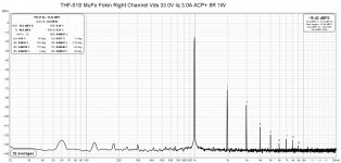
A graph of the Akitika Oscillator at 1V connected directly to a Pete Millet Sound Card Interface which in turn is connected to the Focusrite Scarlett 2I2.

A graph of the Akitika Oscillator at 1V connected directly to a Pete Millet Sound Card Interface which in turn is connected to the Focusrite Scarlett 2I2.
That's a lot better, much closer to 0.0002%.
Try it with the Oscillator directly into the Focusrite, and adjust the level at the Oscillator, and set the Focusrite input at about 11 o'clock. You don't need to have the level at 0dB, which may increase the distortion as it may overload the Focusrite. I usually have the level at -10dB or lower.
Try it with the Oscillator directly into the Focusrite, and adjust the level at the Oscillator, and set the Focusrite input at about 11 o'clock. You don't need to have the level at 0dB, which may increase the distortion as it may overload the Focusrite. I usually have the level at -10dB or lower.

Akitika Oscillator connected directly to Focusrite Scarlett 2I2. Gain on Focusrite at 11 o'clock.That's a lot better, much closer to 0.0002%.
Try it with the Oscillator directly into the Focusrite, and adjust the level at the Oscillator, and set the Focusrite input at about 11 o'clock. You don't need to have the level at 0dB, which may increase the distortion as it may overload the Focusrite. I usually have the level at -10dB or lower.


Last edited:

That's a lot worse. Try changing things. Instead of stacking the oscillator on top of the Focusrite, separate the two. The oscillator may be affected by magnetic fields. Try moving both the oscillator and Focusrite around and see if that changes the distortion level.Akitika Oscillator connected directly to Focusrite Scarlett 2I2. Gain on Focusrite at 11 o'clock.


Well, that's strange that the H2 is that high. What happens if you increase the oscillator output level?
Oscillator at 500mV and 1V.
Another thing that's odd is that I can't duplicate the measurement in post #2164 no matter what I try, and I think I've tried everything...switching cables, changing inputs, moving equipment around. kind of weird.


Another thing that's odd is that I can't duplicate the measurement in post #2164 no matter what I try, and I think I've tried everything...switching cables, changing inputs, moving equipment around. kind of weird.
Last edited:
The 1V may be overloading the Focusrite a bit.
However the 500mV (-5.34dBV) showing higher distortion than the previous measurement at -10.33dBV does not seem like a good thing to me.
Can the setup and results of post #2164 be repeated? (Edit: Whoops, didn't read the previous post carefully).
I wonder whether something has changed with the oscillator?
Another thing to check is to go into REW's Preferences to see if the setup is still correct.
Last edited:
I measure the oscillator with a Keithley 2015 and nothing has changed.I wonder whether something has changed with the oscillator?
Meaning the distortion also measured high or the distortion measured low?
If there is nothing wrong with the oscillator, then your REW and Focusrite setup needs to be checked.
If there is nothing wrong with the oscillator, then your REW and Focusrite setup needs to be checked.
The 2nd harmonic is very dependent on the gain ratios of the transistors on the positive half vs negative half.
The P ch mosfets routinely have less transconductance than the N's so some 2nd will occur. You can minimize this with device choices, for example with the old Harris devices.
At the same time, the 2nd harmonic would likely be negative phase, so you might choose to just enjoy....

The P ch mosfets routinely have less transconductance than the N's so some 2nd will occur. You can minimize this with device choices, for example with the old Harris devices.
At the same time, the 2nd harmonic would likely be negative phase, so you might choose to just enjoy....
Distortion measures low...too low for the Keithley to even measure it.Meaning the distortion also measured high or the distortion measured low?
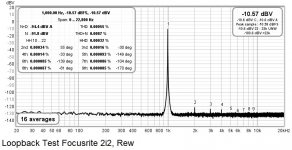
I can get the graph and THD measurements below making a loop back thru the Focusrite using REW.If there is nothing wrong with the oscillator, then your REW and Focusrite setup needs to be checked.
So what does that tell me? about Focusrite/REW setup? Oscillator?
Attachments
- Home
- Amplifiers
- Pass Labs
- An illustrated guide to building an F5