Sort of.Positive tapering = efficiency, low, and big enclosure.
Negative tapering = inefficiency, low, and small enclosure.
Hofmann's Iron Law is still winning.
For a given bulk and pipe length:
Positive taper [aka horn variation] = higher Fp and gain
Reverse taper = lower Fp and gain
Hoffman's iron law still does apply; you have to minimise the physical variables though for it to be a fair comparison.
Since when, and according to whom, with what basis in physics?TL's are fancy BR's. Remember, once a BR's port is at least 72in or 6ft, then BR becomes a TL.
If we're going to get precious about terminoloy, here are some historical & physics based facts / observations: 😉
- A 'bass reflex' is arguably what Thuras derived, & essentially defines those boxes prior to the point Novak, Beranek etc. began to introduce ducted vent types targeting specific alignments, which would later be extended by Thiele, & finally Small, and the latter are strictly speaking better described as those (aka vented boxes). Thuras did in fact use ducted vents on occasion, but these types of early enclosure had different objects in mind to later forms & heavily focused upon system efficiency, per the requirements of the era, which became less significant as power was more cheaply obtained and filter theory allowed size reductions at the expense of [acoustic] efficiency. So these is in fact an argument to call 'BRs' as distinct from later types of vented boxes, just as there is to call 'TLs' distinct from QW (or HW) lines, acoustical labyrinths &c. That's not to say there isn't sometimes overlap depending on the specific type & implementation -just to illustrate how some of these naming conventions can be taken to excess, just as the reverse can be the case.
- 'TLs' are not a strictly defined type in audio and never have been. However, in the majority of cases their basic operating physics is essentially different to that of a bass reflex enclosure, so I'm struggling to understand where this idea is coming from. A bass reflex (and the later vented boxes) are Helmholtz resonators, assuming a uniform internal air particle density and no eigenmodes. A quarter or half-wave enclosure deliberately stretches one dimension relative to the others acoustically speaking to generate and use eigenmodes as their primary / sole resonant mode of operation. In other words, they use standing waves, not cavity, resonance. Were they to be the same thing, then every TL would, ignoring pipe harmonics, have an identical response to a vented box of the same Vb and tuning frequency, which is not the case. QED. There are exceptions, with vented boxes (or bass reflex enclosures 😉 ) that have oversized ducts which are then damped out either to remove pipe harmonics (Onkens come to mind) or for other alignment purposes. But those aren't very common.
- Assuming you're aiming for an aperiodic type of alignment (like Bailey*) then a TL is essentially such a pipe stuffed with the object of achieving a [relatively] flat impedance, minimised [as far as possible] cancellation from harmonic modes & a 2nd order system rolloff until some very low level / frequency where it will finally unload 4th order. But that's just that particular variation on the theme: it's far from an obligation.
- You can have transmission lines far shorter than 6ft. That's just a number pulled out of the air, and also ignores the effect of taper on Fp: the acoustical length of a QW or HW pipe varies on both its physical length and its taper. Nobody said there has to be some arbitary minimum frequency above which a pipe can't be called a QW / HW / TL. If that were the case, we could equally say 'only boxes tuned below [for e.g.] 60Hz are vented boxes: if Fb is higher, that Helmholtz derived box with a ducted vent in it isn't actually a vented box'.
As an aside, you have to be very careful when reading Bailey: his work was clearly superb, but his article, interesting though it is / they are, are not of the same quality. He doesn't provide (and didn't appear to have derived) a detailed design method per se, was sketchy in explaining the details of his objectives & approach to matters like damping (possibly due to limited article space) and didn't make it especially clear in either article that the measurement conditions in the first were with the speaker in 1/4 radiating space conditions in a very large university lab, artifically boosting the LF response, which appears to have been plotted on progressively increasing 10dB, 25dB & 100dB spot frequency gaps, while his 2nd was shown in nominally anechoic 1/2 space conditions.
Last edited:

There’s no offset position , the driver is centered in the pipe and the measured impedance is identical to the simIt's still an offset driver BP6P design.
No? its just a resonator so long it has multiple resonances like a lot of wind instruments. If you fold it back onto itself then the full wave length intervals will clash with the driver output and cause big cancelation dips like a ‘bandpass‘ however?Aren't QW's bandpass enclosures?
Positive flare quarter wave port or tube = TH or BP6S.
Straight flare quarter wave port or tube = TQWP, TQWT, or BP6S.
Negative flare quarter wave port or tube = T-TQWP, T-TQWT, or BP6S.
Positive flare quarter wave BP4 = FLH.
That doesn’t ’tell you ‘ anything. You can describe any type of resonator in any of those sections if you wan?In HR, you can model a BP6P with the Nd, OD, CH, and BP6P functions.
In HR, you can model a TL with the Nd and OD functions.
With the Nd function, you can model TL's without using the segments, just like a BR enclosure. That fact right there tells you they are the same enclosure type. All you need is Vrc/Lrc and Ap/Lpt. Shoot, you can use Vtc/Atc and Ap1/Lp and get the same results.
Last edited:
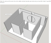
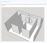
something like this?
what about the distances in red
Attachments
Last edited:
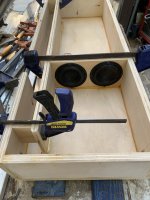
It’s only 4” deep, it doesn’t do anything until about 864hz? I wish I could get a decent measurement off the ‘whole thing’ instead of being stuck out at one of the pipe ends
Last edited:
Positive tapering = efficiency, low, and big enclosure.
Negative tapering = inefficiency, low, and small enclosure.
Hofmann's Iron Law is still winning.
Exactly! Since building it with a tube makes it easy to do so and it's likely the best compromise.
That doesn’t ’tell you ‘ anything. You can describe any type of resonator in any of those sections if you wan?
Yes it does. You cannot model certain enclosures with certain HR functions.
Example, you cannot model a BP6P, Sealed, BR, or TL enclosure with the TH and PH functions.
However, you can model any style BP6S with the TH and PH functions.
The BP6S function does not allow you to model a positive or negative flare TH.
My fault on the quarter wave. Both TL's and BP's are QW's. I meant to say TAPPED QW's are BP6S.
why does ‘positive’ tapering make such an ugly/sometimes useless result after 3x Fb in tapped horns)
Yeah buddy, I hate the ‘names and the ambiguous overlaps in between them . The air (physics)doesn’t give two sh!ts about what humans want to call it so I just rely on the electrical impedance measurements in my junkYes it does. You cannot model certain enclosures with certain HR functions.
Example, you cannot model a BP6P, Sealed, BR, or TL enclosure with the TH and PH functions.
However, you can model any style BP6S with the TH and PH functions.
The BP6S function does not allow you to model a positive or negative flare TH.
My fault on the quarter wave. Both TL's and BP's are QW's. I meant to say TAPPED QW's are BP6S.
if I model my bp6p designs in PH1 with L45 set at 0.01cm it’s fine(as pictured)
Attachments
That TL bit in the Great Sound thing is very out of date, and much of it has been shown to be wrong.
dave
dave
It’s only 4” deep, it doesn’t do anything until about 864hz? I wish I could get a decent measurement off the ‘whole thing’ instead of being stuck out at one of the pipe ends
Top is BW's ODBP6P T type enclosure.
Bottom is an ODTL.
in tapped horns
Do you mean a double tapped horn (after Danley)?
dave
if I model my bp6p designs in PH1 with L45 set at 0.01cm it’s fine(as pictured)
THAT is a BP8P! Nice 8th order!
Not sure, do you have a pic by chance?Do you mean a double tapped horn (after Danley)?
dave
Why 8th? It’s just two seperate resonators 60cm long (folded) and 30cm long(folded) and the cancelation is centered on the total as 180cm/4 in horn response (192 hz) I notice…. So these are actually ‘1/4 wave resonaturs I suppose?
Last edited:
Sort of.
For a given bulk and pipe length:
Positive taper [aka horn variation] = higher Fp and gain
Reverse taper = lower F3 and gain
Hoffman's iron law still does apply; you have to minimize the physical variables though for it to be a fair comparison.
Something has to be the same when comparing the 2 enclosures, either same tune, volume, dB level.
Not sure, do you have a pic by chance?
Word! Maybe he meant double fold TH vs single fold TH.
- Home
- Loudspeakers
- Subwoofers
- An idea: A T-line with both ends open