It’s a minor point. Unlike closed box systems, with open baffle you can’t time align physically misaligned drivers by use of dsp delay.
Thanks for the clarification Peter, it doesn't seem to me that time alignment of the rear wave is that important unless it causes a largish, widish dip in the power response around the crossover frequency, and wouldn't that only happen on axis?
Well, and if acoustic centers are physically aligned in OB construction, front and backwaves will not need dsp delay adjustment. And with higher freq this gets more and more difficult - and vertical angle change will mess it anyway. Backside raditation's coherency is not as important as the frontside which makes the "direct wavefront" towards the listener.
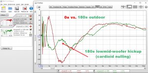
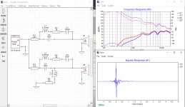
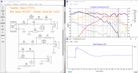
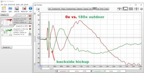
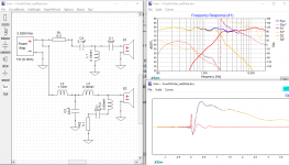
Here are my AINOgradient's 0 and 180deg step responses overlaid (two time scales) Frontside was optimized and notice that low woofer is monopole - polarity is same but on backside there is a hill which indicates cardioid nulling, around xo frequency.
Here are my AINOgradient's 0 and 180deg step responses overlaid (two time scales) Frontside was optimized and notice that low woofer is monopole - polarity is same but on backside there is a hill which indicates cardioid nulling, around xo frequency.
Attachments

Last edited:
This post is to compare a three way design using First-Order Coherent and B&O “Transient Perfect”. Before going further, let's get the terminology out of the way, The word “Coherent” and “Transient Perfect” may conjure up endless discussions as to the meaning but in term of freq. and phase, they all mean the following: the overall response of the speaker as a whole should have absolutely 0 phase shift in the audio band, such as 50Hz to 20KHz. That's it. Nothing more complicated than this.
We should not “mystify” these terminologies to make things more complicated. If the response has zero phase shift, then by definition, it is coherent or if you prefer “transient perfect”. This means that you could call your speaker “transient perfect” as long as it has zero phase shift with however way you arrived at your solution – be it LR4, LR2, first order, or DSP, or whatever way you see fit.
Of course, no real world speaker will have absolutely zero phase shift. It will have some amount of phase shift, but just make sure the phase shift should be as minimal as possible. Since it's an analog world, no exception, some speakers will have more or less at some frequency bands than the others, so one shouldn't get all too worked up over who's better. This post is not meant to say anything the better. Sure 8in will have more bass than 6in but that's something all different.
I won't get into the theoretical aspect of B&O (there are quite a few links that can do a better job), but will touch on things in a more intuitive way. Here's what it comes down to. The B&O approach basically runs the woofer and tweeter in a LR2 roll off (12db/octave roughly) which has the advantage of not making too much demand on the drivers. On the other hand, the pure first order approach runs all three drivers – woofer, tweeter, and mid – in first order (6db/octave roughly). Before going further, some might ask what's the big deal? There are a lot of three way designs so what's so special about the B&O or first-order coherence approaches? Well the difference is the B&O and coherent approaches promise zero (0) or very close to zero in the audio frequency band and therefore will be able to perform a proper “step response” among other things (lower group delay...). A run-of-the-mill 3way approach won't have 0 phase shift because you may have drivers with different polarity.
OK, so we got the definition part out of the way. So what's the real difference between the B&O and first order coherence? The B&O also promises a zero phase shift (just like first order coherent), but using 12db/octave roll off not too unlike most speakers out there, like having a cake and eat it too. But I was playing with some simulations doing something similar to the B&O way, but I found something that I didn't quite like – like a devil's promise but with a hidden agenda (hahaha just joking!).
Here's the intuition part, the B&O approach runs the woofer and tweeter at 12db/octave, with a hole in the middle of the frequency band (somewhere between 500Hz and 3KHz), and the mid driver acts as a “filler” to fill in the whole no pun intended. The steeper the roll-off of the woofer and tweeter, the “larger” the hole, and the mid “filler” the more has to work to fill in the hole. And here's the devil's little secret that requires you to sell your soul (hahaha joke!). But seriously, that's what it comes down to. There's really no free lunch. In the B&O approach, the woofer and tweeter may not work very hard at 12db/octave, but the mid still has to work pretty hard at 6db/octave roll-off, which means that the mid is still in first-order mode, the whole time.
But that may not be all. Here's the hidden part of the devil's promise that may not be that obvious to the innocent xover-er (joking!). On the upper mid where the mid and the tweeter have to integrate at the cross-over point, the tweeter has been running at 12db/octave or there about, but the mid has always been running at 6db/octave and has to match the tweeter 12db roll off, so in the real world, the sound may not be that well integrated on a listening test due to the unsymmetric of the two roll-offs. Of course it will be implementation dependent and I guess if you're pretty good at xover, or making your cabinet, you may be able to out-smart the devil (joking!), by making them better integrated either electrically or acoustically. Based on my own listening experience, at the upper frequencies where the wavelengths are shorter, these types of mismatch can be made worse by the vertical listening level, and if not paid attention too, the treble and the upper mid may sound like they come from different source. Base on my simulation, I did have a hard time matching the phase of the tweeter and mid at the cross over point. Sure, I did have the frequency and phase did come out OK, but what I did was not that natural.
Having reading some of the comments regarding the B&O, there were comments along the line of using a small mid so that it is able to play at higher frequencies, or having to resorting to the usage of full range driver. Find full range drive may not be easy, at least the quality one. Also having a small mid range may compromise the lower frequencies at least some I have heard sounded somewhat “thin” especially with male voices! I guess in this case the devil's promise is a beautiful woman but with small mids (joking!). You can go around this small mid limitation by having a closer overlap of the woofer and the tweeter so the mid does not have to work hard at the lower frequencies, but then the woofer has to work harder at the upper frequencies therefore an 8in woofer may have a problem. Anyway, there are always trade-off, and as I said, there's no free lunch and the devil at the end will just fool you. Or to make a compromise, you could have a 7in. woofer which will work up to 1KHz to integrate to a 3in mid and so to relieve the mid lower frequencies.
Of course first-order filters are not any easier either and may even be harder than the B&O. It places a lot of demands on the drivers, and only a few drivers perfect enough that can meet the strict requirement of first-order 6db/octave roll-of. And realistically the other limitation is a first-order coherence can have at most 3 drivers – tweeter, mid, woofer. Anymore and the problem may be impossible. You can add a subwoofer at the end but that's something different and can be done afterward. In this case, the promise of first-order 0 phase shift is there, but at least you know upfront all the hard works, and no hidden surprises. During the simulation, I actually found going all first-order having a more “natural” integration between all the drivers and some way easier since they're all running at 6db/octave roll-off and all symmetric.
In my next post or two, I'll attached two 3way xovers: one is all first order (at least on the electrical side), and a B&O LIKE approach. My “B&O” version does not have the typical LR2 roll-off. Probably more like LR1.68 or there about but enough to illustrate the point. The example also illustrate how “harder” the mid in the B&O vs. a first order approach.
I then will compare two different xover approaches to having “B&O LIKE” way. One have a steeper roll-off on the woofer and tweeter, and the point is to illustrate how “harder” the mid has to be driven to make up for the steep roll off of the woofer/tweeter, everything else being equal.
A skill I learnt from high school finally paid off 🙂
B&O “Transient Perfect”
Last night I saw a devil
He promised me of untold riches
Of beautiful women of perfect proportion
Then I woke up a fleeting dream
First-Order Coherent
Having awaken from last night nightmare
With aching bones and creaky joints
Lazily walking to my messy lab
Facing all the messes and beauty world
Making this simply a first order filter. Why make anything up. The industry has spent over 100 years using the same terms.let's get the terminology out of the way, The word “Coherent” and “Transient Perfect” may conjure up endless discussions as to the meaning but in term of freq. and phase, they all mean the following: the overall response of the speaker as a whole should have absolutely 0 phase shift in the audio band,
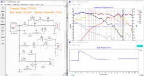
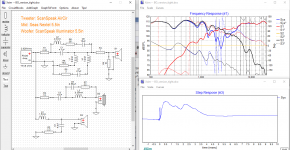
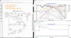
I here have two versions of a three way speakers: one using first-order and one using a "B&O" like approach although it's not quite BO LR2 but probably more like LR1.68 lols.
A few words regarding to BO and all-first-order filters. There are quite a lot of similarities between them which is not a surprise since they are all derived from basic filter theory. It's not like BO comes from another dimension. If you think of them just as basic math, Laplace transform, freq. and time domain manipulation … and so on then you probably won't treat them as a mystery.
Notice the tweeter and woofer of the first order work harder vs. the BO but the mid in the BO has to work harder. So if you use BO approach, you probably need a small mid to run slightly at higher frequency.
Another disadvantage of BO is it can only be used in a three way albeit with a rather small mid, whereas all-first-order can be 2way as well. One more advantage of all-first-order is that the mid can be used with more options … such as larger mid driver size.
Another observation is although the tweeter in the first order version works harder, it has a "better" impulse response with less secondary "ringing". Being second order, the tweeter in the BO has a slightly more under-shoot.
Attachments
Here is two different versions of "BO"-like filters. One with more steeper roll off from the woofer and tweeter, but the mid is then required to run slightly harder at the low end and high end frequencies. Anyway, definitely a trade off.
Attachments
First, no speaker can have anywhere close to zero phase across the audio band of the speaker unless it uses digital phase correction. It doesn't matter if it's passive or active analog, or digital implementation of these "analog" derived crossovers. The best that can be achieved is elimination of the crossover induced phase nonlinearity which renders the system minimum phase. As I stated earlier, the phase of the speaker will then be determined by the low and high frequency cut offs and the order of the of the roll off at those limits. For example, a sealed box system with Fc = 30Hz and some Q will have the low frequency phase response similar to a 2nd order high pass filter with the same FC and Q. The high frequency phase will similarly be that of a low pass filter with the same Fc and roll off. You can easily simulate this as a band pass filter to see what the phase looks like.
Often you see phase plots that look more linear than what I have stated. This is usually because more than just excess phase is removed from the measured phase as is often shown by a turn up of the phase at high frequency. This is purely misrepresentation of the system phase response
Second, the B&O filler driver approach does not require LR2 woofer and tweeter filters. I generalized the approach back in 2002
GenFiller
Then there is the 2nd order approach of Small which I also generalized back in 2001
CrossoverdocN3
The problem with all these types of crossovers is that none of the transitions between drivers is such that the HP and LP section sum in phase, like the LR4. Thus, they all have polar response which exhibits SPL levels above the axial response which can cause less than satisfactory sound.
The best way to achieve this type of speaker is to start with a crossover the sums on phase, like the LR4, and then implement these crossovers digitally as linear phase filters.
And, of course, we are always referring to the acoustic side of the filter matching the targeted response, not the electrical filter.
...and vertical angle change will mess it anyway. Backside raditation's coherency is not as important as the frontside which makes the "direct wavefront" towards the listener.
This is the reason why also OB could have delay correction with DSP if physical acoustic centers are not exactly time aligned to listening spot in front. Rear side produces close to same sound power for ambience regardless of less controlled timing and response to exactly 180 deg axis, and total sound power should be designed balanced anyway.
Less pressure to exactly 180 deg could be even advantageous in practice, though not so idealistic as a design target by looking single 180 deg response only.
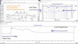
Here are my AINOgradient's 0 and 180deg step responses overlaid (two time scales)
...measured with Umik-1 and normalized by REW without timing reference so information is something else than timing differences.
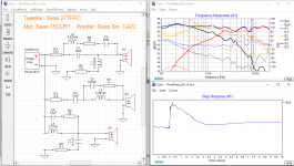
Along the line with the previous example, here is another similar situation where the woofer and tweeter having a 2nd roll off but the mid having to shoulder a wider band. You have to adjust the 2nd roll off rate depends on your own implementation and whether you want to adhere strictly to the "B&O" having the exact LR2 roll off. I guess the common observation is the mid needs to play at a higher frequency range if the woofer and tweeter having a 2nd order roll off.
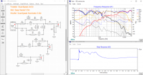
I put together a couple of "monitor" cabinets. One is used for the bass, and the other is used for the mid and tweeter. Ignore all the peaks and dips since I think the measurements had a lot of room reflections. Maybe should retake the data but probably won't make much of a difference in term of the general xover design.
I put together a couple of "monitor" cabinets. One is used for the bass, and the other is used for the mid and tweeter. Ignore all the peaks and dips since I think the measurements had a lot of room reflections. Maybe should retake the data but probably won't make much of a difference in term of the general xover design.
Attachments
What's the purpose of those crossovers in the tweeter path?
I just can't figure out why complexity arises...
But that's also probably due to the complexity of doin' a good two-way, when a three-way would be sufficient to cover the expectations of a listener. Dunno what to expect from a B&O three-way but mid configured a la...B&O. AllenB often says that resistors do put phase alterations in circuits, so I'm tempted to say: bring some Rs
Here is two different versions of "BO"-like filters. One with more steeper roll off from the woofer and tweeter, but the mid is then required to run slightly harder at the low end and high end frequencies. Anyway, definitely a trade off.
Note: You only get the promised performance form the BO& filter if you have the exact steepness and phase as prescribed. AND... you need to have it acoustically so just using a L and a C doesn't necessarily mean you get 12 dB/oct rolloff.
You mention LR - are u sure it shouldn't be Butterworth? I dont recall and to lazy to look it up. It swing a lot of concepts and terms but I get the feeling you maybe don't really master them but rather "wing it" a bit - how is it?
Good luck and much fun anyways!! And don't forget to report on your listening impressions - these might be the most interesting as the theory is well known to many here.
//
---
...measured with Umik-1 and normalized by REW without timing reference so information is something else than timing differences.
If individual drivers' sweeps would have been overlaid, we might have the problem that kimmosto suspects.
But those step responses come from two sweeps of a complete 4-way speaker measured at same setup. REW aligns them automatically in overlay, by first peak. So, I am confident that they tell the interplay and relative acoustic delays of "ways" (Red frontside 0¤, green backside 180¤)
In a series of vertical off-axis measurements (not shown), we can see how step response changes as relative timing gets messed (and spl response gets wiggly), because of increasing physical misalignment.
Attachments
Last edited:
And here is the real problem with the B&O approach. As was pointed out, the filter function responses are targets for the acoustic response. Since the tweeter filter will required a 2nd order acoustic response, and conventional tweeters already have a natural 2nd order roll off, the filter must be a simple Fc, Q shifter filter, also known as a Linkwitz transformation. These types of filters are usually implemented actively alter the fc and Q of sealed box woofers, but can be applied to tweeters too. The problem should be apparent. Assuming the tweeter's Fct is above the desired crossover Fcc, the filter will roll off between Fct and Fcc, but below Fcc the filter will have flat response. Assiming Fct is an octave below Fcc that means the tweeter will receive the full range signal below Fcc attenuated by 12dB.Adding a HP filter somewhere below Fct to further attenuate the signal screws up the phase. The problem is the tweeter excursion at low frequency, if it can survive, will increase distortion significantly.
Similarly, with the filler driver there are two issues. A typical cone driver used as a filler will have a 2nd order HP roll off at it's Fc and will roll off at at least 12db/octave at hog frequency. All this has to be shaped to a 1st order BP acoustic response. The problem here is worse because with the 1st HP response fort he filler means that below the filler's Fc the response will actually have to be boosted meaning that below fc the driver excursion will increase as the frequency decrease >>>> distortion if the driver can survive.
The net result is that although these B&O like systems can produce excellent impulse response and very good square wave response of a portion of their bandwidth, they can not play as relatively high SPL without at least high levels of distortion.
I admire Andy2 for the effort he is making. Having been through it I know the effort. But having done it, other than for the exercise, it's a complete waste of time and money to pursue this approach for a quality speaker.
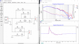
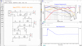
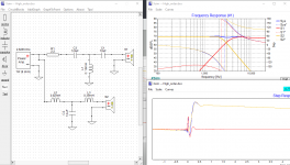
I've reworked the xover so that it might be a bit more "B&O" original intent. Basically I move the woofer and the tweeter closer together, so the "hole" in the middle is narrower, which also reduces the work load on the mid. You can see the mid upper frequency response drops off a bit more vs. my previous version. Not only that, the low frequency of the mid also rolls off a bit earlier as well.
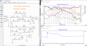
1. First if I mute the mid, then there would be a "hole" in the middle of the frequency band. See the first attachment.
2. Then, if I now invert the tweeter, then it would look like any typical 2way using a 2nd order roll off, as if the mid driver is not there. The only problem is there is gradual phase shift toward 180 degree at the freq approaches 20KHz. Also the step response shows the typical 2way with the tweeter inverted polarity. Of course what we want is 0 phase shift across the frequency band.
3. Now if I turn the mid back on, then making all the drivers positive polarity, with the exact xover, now you have "0 phase shift" at the same time having the same proper frequency response as the 2way version in #2. See the third attachment. Of course, because of room reflection, diffraction and so on ... so the phase shift will bounce around 0 degree. The worse case is about +30 degree at 6.3KHz which happens to be at the dip of the diffraction due partly to the step-baffle. Therefore in order to have very minimal phase shift, the baffle needs to be optimized to minimize diffraction and also better align the driver acoustic centers. (There is a bit of a spike in phase at around 1.3KHz probably due to the dip in room reflection and for whatever reason the dip just happens at the same place for the mid and the woofer.) Also further optimization of the xover to further improve the phase shift.
Attachments

Just another comment. The B&O concept is not unique. It is just another form of subtractive transient perfect crossover. You can take any pair of 2nd order filters, with any Q, and any Fc, sum them and subtract the result from flat, zero phase, and you will get a filler driver with 1st order roll offs. The HP and LP don't have to have the same Q or the same Fc. They don't even have to have the same order. The only question is if the resulting band pass filter for the filler is "reasonable". The band pass filter will always be a 2nd order band pass (1st order roll offs on bot sides), but the gain may be greater or less than unity, and the shape of the amplitude response in the crossover region may not be smooth.
While I respect what Andy2 is doing, everything the he is doing has been done before. It's a complete waste of time and effort. It doesn't not lead to a better speaker.
While I respect what Andy2 is doing, everything the he is doing has been done before. It's a complete waste of time and effort. It doesn't not lead to a better speaker.
I have learnt early on
Every coin has two sides
Now I know of life
And of hate and desire
Every coin has three sides
And there lies the rub
I'll use this post to talk a bit about the step response which is somewhat of a controversy. The “coherent” or "transient perfect" camp would use it to criticize that if a speaker cannot produce a proper step response, then it's all wrong. The other side would respond that music is not a step response so the argument of a step response is irrelevant.
As with anything, there's some truth to both sides. But before anyone coming to any conclusion, let's look a bit at the step response and may understand it a bit more.
In engineering, we always look at everything both in the frequency and time domain. Sometimes it's easier to look at things in frequency domain and sometimes in time domain. A good engineer will always look at two sides and figure out what's the best solution. As Hegel put it: thesis, antithesis, and synthesis. A good example is phase noise and jitter measurement. Jitter usually is associated in time domain whereas phase noise is in frequency domain. Sometimes it's easier to look at one vs. the other. Sometimes the solution lies in the phase noise plot, but sometimes it's easier to solve problem in the jitter plot.
In speaker design, it's a bit of a weird exception where most people will mostly look at frequency response and always almost disregard time domain. Frequency domain is the frequency plot of the speaker response which most people probably would be familiar with. The time domain is mostly in the step response or its cousin which is the square wave. For example, a dip in the step response will show up accordingly to the dip in the square wave. I think whether which camp you're in, I think it's good to see both sides, or if you prefer, know your enemies lols.
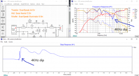
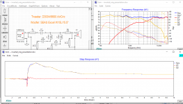
1. Let's see the first attachment. Most of us used to read a plot from left to right, low frequencies to high frequencies so that's our basic instinct. But the step response is the complete opposite. You read the low frequencies from right, and the high frequencies from the left. For this attachment, notice that on the frequency plot, the low frequencies have a lot of room reflections with all the peaks and dips, and correspondingly, the tail end of the step response takes a lot of time to settle because of the reflections.
2. Let's see the second attachment: This comes from another measurement where the low frequencies are a lot cleaner. Therefore the tail end of the step response settles much quicker. That's how I like it!. So you can see the correlation between the two.
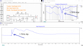
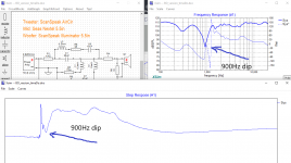
3. The next three attachments will give you a visual picture of which part of the frequency response corresponds to the step response. I intentionally created three dips to show the cross correlation between the two. The frequency plot shows the dip in the frequency at 900Hz, the next one at 1.7KHz, and the last one at 4KHz. Correspondingly, you see the dip on the step response goes from right to left as the frequency goes from low to high. The rest is fairly intuitive. By the way, I wish Xsim would give you better resolution in the step response so I can zoom right in, but anyway, I guess it's enough to illustrate my point.
But so far, it's fairly straight forward, each dip in frequency domain corresponds to the dip in the time domain. Nothing too weird.
But it gets a bit weird when you start using high order filter and the frequency plot may turn out be straight and has no dip and looks proper, but the step response may show dips. I'll make that my next post.
Attachments
God does not play dice
But he plays the devil
And knowing where he plays
You know where's the rub.
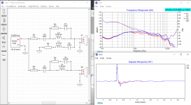
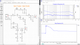
Let's look at the step response of a simple 2way, but this time the tweeter is reverse polarity. As seen the frequency response seems fine with no dip. On the other hand, the step response shows an initial dip, and as we talk about in the previous post, the initial dip is in the high frequency portion. See the blue trace as the overall system step response.
For this example, I intentionally made the cross over frequency pretty low at 1KHz so it is easy to make an demonstration. The initial reaction of the “coherent” camp would be like, “see, the treble and the low frequencies are all opposite therefore it is inferior and I would be surprised it will make music at all … blah blah blah ...”. Well not so fast though.
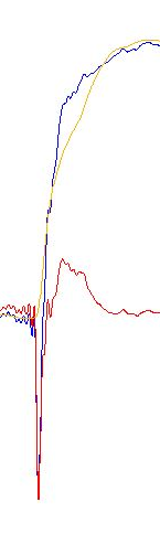
In the attachment #1, you see the overall speaker as the blue trace. But looking closely, you should also see the step response of each component: the blue trace, the yellow trace, and the red trace.
Blue – system
Yellow – woofer
Red – tweeter.
I will zoom in the step response so you will clearly see each component. First notice from the frequency plot, the cross over point is at 1KHz. Now if you look closely on the step response, you see that only initially that the tweeter goes opposite of the woofer (high freq), but then both the woofer and tweeter go up together at 1KHz and before that. See the “cross over” on the step response at 1KHz. Everywhere on the right of the cross over point at 1KHz on the step response (or on the left of the frequency plot) is where the tweeter and the woofer all go up together. Or you could say below the cross over point, they all go up together and only after the cross over point, they start to slowly diverge. So to say both tweeter and woofer go opposite is not entirely true, you have to take into consideration the frequency band where the overlap occurs.
For this example, I used 1KHz cross over point as an example. But in most speaker, the cross over point is probably around 3KHz so you have a much large portion of the frequency response where much of the music presides, or where it matters most, that the tweeter and woofer all go up together.
On the third attachment, here I go back to 3KHz cross over. 3KHz is even better, and up to 3KHz, both go up together as opposed to 1KHz. So does it mean the higher the cross over point, the better because you get more frequencies where both the tweeter and woofer go up together?
I guess this is the “gray” area. Where does it matter? Where and how much does the phase shift become in issue? We know that MP3 is inferior because of the extreme phase shift at high frequencies. Everytime, I listen to mp3, the treble sounds very “digital” which is something I hope should not be debatable. Not only that, the bass always sounds mushy also because of the phase shift at low frequencies. Also early digital in the 1980's sounds very nasty, because of the extreme brick wall filters were used and caused excessive phase shift at high frequencies. Now we have upsampling and much shallow filters so it's much better now (among other things of course).
I suspect in the MP3 case, the phase shift at high frequencies is rather extreme. In this particular example, the maximum phase shift is only 180 and only at 20KHz so it's not that bad. Maybe our hearing can be tolerable with minimal phase shift vs. mp3 extremity.
Unfortunately it's not black or white thing. Phase shift in itself may not be “bad”, so I guess the answer is somewhere in between ...
And therein lies the rub.
Attachments

“When they go low, you go high ...” Michele Obama made famous by Hillary Clinton.
Now look at an example using high order filter. For this, I use a third order electrical filter. I will also use ideal driver because it's a bit cleaner and easier to see.
As expected, the phase shift should be steeper vs a first order filter. Interestingly, for this example, both drivers are in positive polarity, so you would expect they are able to perform a proper step response right?
Actually because the nature of high order, even when the drivers in the same polarity, they cannot perform a step response.
See the first attachment. And you can see here that with the same 2way, even with positive polarity, the step response looks quite a bit messy. You see that the initial spike is from the tweeter which is a full 360 degree ahead of the low frequencies. And then there is a dip in the step response from the tweeter, then only at this time, both the tweeter and woofer both go up together at the cross over at 3KHz.
So you can see as you go higher and higher in filter order, things look a bit complicated because of the higher phase shift. Sure at below the cross over point, the tweeter and woofer go up together, but after that the phase can look a bit dicey.
I also attached an example using real data but it's more or less the same.
Again, we go back the question from my previous post, where does it matter? How high, or how low does phase shift matter? Or does it matter at all?
Attachments
Last edited:
- Home
- Loudspeakers
- Multi-Way
- An exercise in converting a speaker to time-phase coherent