MC12 reveals to us:
quasi - open loop case - under loadcondition
Vuo = +55dB
f-3 = 60kHz
#
CL Case:


The upper or lower half /branch are not really recommended as single-ended amplifiers!
HBt.
quasi - open loop case - under loadcondition
Vuo = +55dB
f-3 = 60kHz
#
CL Case:
The upper or lower half /branch are not really recommended as single-ended amplifiers!
HBt.
2.5Wrms as a true single-ended class A 0.1% THD amplifier, more /or better is not possible.
CLG = +19dB

CLG = +19dB
You know what. I think the design is more the result of marketing. The performance was never the 1st priority.
Here I am pretending the marketing person.
What sells? Not a class-D amp with 0.006% thd for sure.
1. It has to be symmetry. A good looking circuitry must make better sound. Right?
2. No miller compensation. "Globle Negative Feedback", and "Miller Cap" are 2 forbidden phrases from HIFI.
3. Specs? It measures better than a McIntosh MC275. It doesn't matter!
Last edited:

We must not forget the housing design and, above all, the touch temperature.You know what. I think the design is more the result of marketing. The performance was never the 1st priority.
#
And while we take the MF-A1 apart and strip a legend of its aura, it plays happily and cheerfully.
Canadian Brass
play Monteverdi to Mozart


Yep, that’s one of the options.We need more current, Iq approx 1.25Adc
24v rail, into 8 Ohm, maxes out 3A. Push pull class-A, Iq 1.5A.
Probably not with the original chassis and the power supply.
@wahab
The designer was:
Great Grandmaster Tim de Paravincini ...
We need more current, Iq approx 1.25Adc.
😱
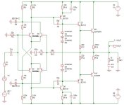
This amp is basicaly a differential driving a high current VAS, the OS is a transimpedance stage and as such has a high output impedance, so with a 8R load the OLG is 46dB and with a 80R load it logicaly increase by 20dB at 66dB and 83dB with a 800R load.
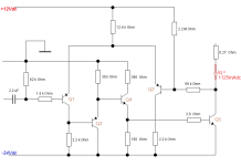
And no amount of current will change this characteristic, the amp is badly designed and that s all, he should have
used something like this instead and even if not fantastics he would had got much better numbers.
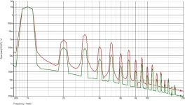
Edit : i add the comparison between the original schematic, in red the original MFA1 and in green
the much simpler schematic in this post, level is 10.5V pk/8R, bias currents are 1.08A for the original
and 0.7A for the one in this post.
Attachments
Last edited:
I had an A1, and while it sounded O.K on small speakers, the sonics were not to my liking. It’s shortcomings were obvious when it was used on higher-end speakers and studio monitors, where it’s “sound” dominated the playback.Distorsion of this schematic should be huge, beside MFA1 has never been a good design, and never will be,
it s well below other such symmetrical diferentials that were published roughly 40 years ago.
In reflection, I kind of feel the class-A part was hoopla that generated waste heat doing little, except imitating a George Foreman grill. It did not have the detail, airy treble or wide stereo separation I would have expected based on the reviews, and deep bass was non-existent. It was a quick sale when I’d had enough of it.
I wish the OP luck and hope it turns out better than the original design.
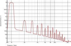
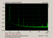
Realworld spectrum:
But, what I have is measurements of my own specimen, slightly tweaked
If you're in mood, compare these with those linked in previous post
Forgot to measure gain, but have this:
Vout 4Vrms@8R translates to 3V858@4R
thus Rout=0R3
DF 26@8R, 13@4R
so -...
- line stage tossed out, VolPot connected as usual, JFet buffer after
- emiter resistors for outputs are halved in value ......... altered MOhm resitors, to set Iq back to standard
- altered NFB to have less CLG, more proper to today's sources
- pretty much all elcos replaced with new, solid caps instead elcos where possible
If you're in mood, compare these with those linked in previous post
Forgot to measure gain, but have this:
Vout 4Vrms@8R translates to 3V858@4R
thus Rout=0R3
DF 26@8R, 13@4R
so -...
Last edited:
Dear Bernhard,
as usual, I don't understand your answer - with the best will in the world I can't make sense of it.
#
However, we can play a little bit with the resistance values of the original - and possibly get a better A1, or a more reliable candidate?!
HBt.
Psst
as usual, I don't understand your answer - with the best will in the world I can't make sense of it.
#
However, we can play a little bit with the resistance values of the original - and possibly get a better A1, or a more reliable candidate?!
HBt.
Psst
On the contrary, I don't know what a fat dripping sponge cake dipped in honey sounds like, but if a transfer were possible, which of course it isn't, then you're completely wrong!this thing sounds like an oily fried dough ball dripped with honey.
Attachments
On second thoughts it could do some good as home guitar amp, this would eventualy fit a Gibson 335/345,
but for HiFi purposes it s perfectly inadequate unless it is used as a tutorial to display what is to be avoided.
but for HiFi purposes it s perfectly inadequate unless it is used as a tutorial to display what is to be avoided.
This amp is basicaly a differential driving a high current VAS, the OS is a transimpedance stage and as such has a high output impedance, so with a 8R load the OLG is (...)
Just like the simple Lego building block "the emitter circuit" - and this is absolutely load-dependent.
But ...
😢On second thoughts it could do some good as home guitar amp, this would eventualy fit a Gibson 335/345,
but for HiFi purposes it s perfectly inadequate unless it is used as a tutorial to display what is to be avoided.
Now you're really putting the beautiful Musical Fidelity A1 down. Which at 20 peak watts has just an THD1k = 0.03%, see posting #47 (G+18,5dB).
Should we now be sad for Heinz L., the CEO of MF?
HBt.
as usual, I don't understand your answer - with the best will in the world I can't make sense of it.
On the contrary, I don't know what a fat dripping sponge cake dipped in honey sounds like, but if a transfer were possible, which of course it isn't, then you're completely wrong!
Attached an example from the link in my above post.
The spectrum very well correlates with the sound representation of the amp.
Translation of the honeyball: The sound is overly warm, sweet and oily.
I had more than one A1 and I know what I´m talking about.
Attachments
Last edited:
- Home
- Amplifiers
- Solid State
- An A1 descendant - a relentless analysis