
I fear
that we could stray too far from the master's original intention if we unduly modify the differential point (i.e. the differential pair, LTP, IPS) and also convert the output stage into an EF.
Nothing would then remain of the original character or spirit of a "Tim de Paravincini", the ideas of an "Antony Michaelson". A successful "reboot" is characterized by not having proceeded too radically.
HBt.
If we don't manage to push the distortion below the 0.000x % mark, then the remaining distortion must be harmonic, i.e. not dissonant.
Which brings us back to Hiraga, Kaneda or JLH & Pass.
In the first instance, we don't want AB or B operation class (we want to avoid the so-called transfer /crossover distortion under all circumstances), in the second instance a harmonic distortion of up to 0.5% may remain - but we also want this to be in the range <0.05%.
We are interested in the distortion spectrum and a flat THD curve as a function of the fundamental frequency.
Is that correct?
HBt.
Psst
A perfect IPS (as a differential pair) deletes all even multiples, the harmonic ones. If "Tim" had wanted that, he would have invented the "Blameless Amplifier", and not D. Self.
Last edited:
This is the symmetrical classic - thank you @wahab !
But the whole joke about the A1 is its two-stage VAS, i.e. IPS and OPS together form the VAS - transconductance.
And we should definitely keep that up. We have to live with a very specific (and defined) residual distortion, which is what we want - comparable to the AN39 or the Alpha Nirvana Killer project, "the Beelzebub/babe".
This is the only way to ensure a marriage-like connection between the two partners (amplifier and loudspeaker load), i.e. there are suitable and less suitable combinations, the user is always on the lookout for the right combination. A trick we all know, which our high-end dealers in particular welcome.
greetings,
HBt.
Last edited:
If you work on the original PCB, I think the first thing you can do is to modify the feedback network. As #82 shows, add the transitional RC network. At audio frequency, get feedback through the cap C1, C2. At DC, get feedback through the R3, R4.
As a well branded product, there is value to keep it stock. I fully understand that.
As a well branded product, there is value to keep it stock. I fully understand that.
Last edited:
Yea, using VAS as OPT is hard to swallow. Not even mention it is a class-AB VAS.But the whole joke about the A1 is its two-stage VAS, i.e. IPS and OPS together form the VAS - transconductance.
And we should definitely keep that up. We have to live with a very specific (and defined) residual distortion, which is what we want - comparable to the AN39 or the Alpha Nirvana Killer project, "the Beelzebub/babe".
This is true in all respects and at the same time two single-ended amplifiers stand opposite each other as mirror images, with their own GNFB networks, connected only to the ac input node and the dc output node.Yea, using VAS as OPT is hard to swallow. Not even mention it is a class-AB VAS.
An ingenious idea.
Reboot
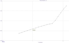
THD(1k), 10Wrms
is now less than 0.0002%
Thanks to the classic current mirror and the huge OLG, and all in true push-pull class A operation.
Quite simple.
After "Bernhard or wahab" provide confirmation of my assertion (= MC12), "M0rten" could get to work.
☕🧙♂️
THD(1k), 10Wrms
is now less than 0.0002%
Thanks to the classic current mirror and the huge OLG, and all in true push-pull class A operation.
Quite simple.
After "Bernhard or wahab" provide confirmation of my assertion (= MC12), "M0rten" could get to work.
☕🧙♂️
Attachments

Thanks to the classic current mirror and the huge OLG, and all in true push-pull class A operation.
Reducing THD by increasing OLG by adding mirrors is exactly what you disliked in another of your threads. 🙂
This is true in all respects and at the same time two single-ended amplifiers stand opposite each other as mirror images, with their own GNFB networks, connected only to the ac input node and the dc output node.
Voltage controlled current sources with feedback, to be precise.
You're not angry with me for that now, are you?Reducing THD by increasing OLG by adding mirrors is exactly what you disliked in another of your threads. 🙂
The aforementioned “Stellema thread” was simply not one of our two gems, as we both hold no grudges and “Stellema” led (and will lead in the near future) to the 25Watt Krill ... it's all good. There's no way I'm a guy who doesn't know or appreciate the blessings of the current-mirror.
😉
In the current political situation, we can no longer tease each other (North vs South), we absolutely have to pull together - united.
greetings,
HBt.
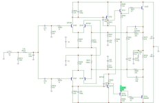
Just for your reference. Fully Symmetrical Blameless Amplifier, based on my conceptual design in #82. I know you have opted out this EF2 option. It is still good to see how it does when you go all in with the symmetrical topology.
VBE multiplier is created through input stage. Thus, the bias on the VAS is fully regulated.


VBE multiplier is created through input stage. Thus, the bias on the VAS is fully regulated.
Last edited:
Somehow I feel responsible to emphasize once again that nobody is asked to take apart their existing MF-A1 now!
A flawlessly functioning A1 is a fine thing. To subject it to a transformation (a major surgical operation) now, to turn it into a PP-EF in a panic ... totally contradicts the concept (the design philosophy) of the original MF-A1.
This thread is just to outline options of what you could do if you want to rebuild a quasi A1 and boost or modify it at the same time - in various directions.
The A1 concept is a very exciting and at the same time a huge field to plow, always with a handful of joy.
best regards,
HBt.audio
This one is my sketch,
my current suggestion, with which one could start the experiment: "newA1, a reboot 2025".
The modifications are so drastic that only the skeleton, the topology is reminiscent of the original - the gender has been completely preserved, and the heat development is still impressive.
The DNA remains hidden, but it is there!

I wish every DIYer who dares to tackle this project lots of fun and success - with an unusual concept.
HBt.
my current suggestion, with which one could start the experiment: "newA1, a reboot 2025".
The modifications are so drastic that only the skeleton, the topology is reminiscent of the original - the gender has been completely preserved, and the heat development is still impressive.
The DNA remains hidden, but it is there!
I wish every DIYer who dares to tackle this project lots of fun and success - with an unusual concept.
HBt.
- Home
- Amplifiers
- Solid State
- An A1 descendant - a relentless analysis