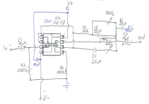
Sounds like it could be oscillating to me, do you have full schematics of the preamp and output?I tested everything together and it is not good. It is clipping, amp is much warmer.
Need the volume pot between the pre amp and power sections. With the LPF filter ahead of the volume pot. Possibly another LPF ahead of the preamp. There is likely poor grounding - it usually happens any time a circuit is spread out over hell and gone. Often it has to be band-aided.
Yep, it is oscillating, it had smilar problem before...Sounds like it could be oscillating to me, do you have full schematics of the preamp and output?
Here is the schematic. It has very sensitive tone control feedback loop. @wg_ski designed this for me, he just replyed with the solution as I write this:

Ok, would "1Kohm & 330-470pf" as @NanoFarad advised earlyer be good for LPF? Will add volume pot.Need the volume pot between the pre amp and power sections. With the LPF filter ahead of the volume pot. Possibly another LPF ahead of the preamp. There is likely poor grounding - it usually happens any time a circuit is spread out over hell and gone. Often it has to be band-aided.
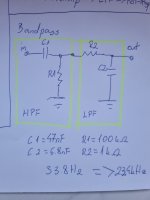
I would also like add HPF bellow 30hz, would it be beter to do it before preamp or amp? Would 100k and 0.047uF be good values? I calculated that this is 33hz cutoff, but I think that impedances around the filter affect it and I should account for that?
Grounding is done in star pattern at the power supply, I didn`t connect signal ground to both sides (just one for wire insulation) to avoid ground loop.
Basicly just one gnd from preamp and one from amp to the PSU, nothing else between the boards.
"For the volume pot the twisted pair goes to its output (wiper and ground) side. " from #123, should I connect ground to the psu or to the amp board?
Last edited:
Oh, thats alot different of what I ever did, I will need to seperate some grounds on boards first, but will do.
EDIT: quick look at both schematics showed that only 2 capacitors on vs+ of the TDA need seperate gnd. Does it makes sense to do it still?
EDIT: quick look at both schematics showed that only 2 capacitors on vs+ of the TDA need seperate gnd. Does it makes sense to do it still?
Last edited:
Yes, it was mentioned before, in #139 that I should do better bypassing, I didn`t do it instantly and then totaly forgot about it. Will do also.
It`s getting late here, tomorrow I will do gnds, bypass, LPF, volume pot and report back, I`m sure all that will fix the problem.
It`s getting late here, tomorrow I will do gnds, bypass, LPF, volume pot and report back, I`m sure all that will fix the problem.
I'm a bit late to the party, but what exactly is the reason you want to 'modernize' this amp? I am sure the original germanium version sounds great, and the transistors you can still find quite easily.
TDA2030 is not exactly modern anyway..
TDA2030 is not exactly modern anyway..
Hy, old amplifier didn`t sound good, I replaced all problematic components one should in old radio. I revisited and tryed to find the problem 3 times over 5 years. In the end it did sound much better, but it is just not good.
Keep in mind that origin is Yugoslavia, 70s, stuff was made as cheap as possible in order to be reachable to working class back then.
Tuner was good, infact really good, but FM reception in my area got really bad in last years.
I searched for a tuner that could be controlled by MCU to replace original.
That means that it would not stay at simple restoration project anway...
And it is intended to go in the kitchen, it will play all day, every day, unsupervised. Probably for years and I would like it repair free.
So the idea came to make radio better with newer technology.
-The best tuner that I could find and make it work; auto-seek, presets, squelch.
-Arduino for MCU... because I know this stuff.
-Motorised scale pointer; ended up with using original string and wheels; stepper motor to turn it.
-newer amplifier that would at least to some extent mimic old sound
And the result as I listen to it right now is good. Sound is much much better, even without preamp, just pc eq.
I know how those radios sounded in general, they were everywhere when I was a kid. some sounded a bit better than my did stock, but not drasticly.
As for TDA... this is exactly the time era where I like to stay with audio.
Last edited:
No need to even go that high if you are driving with an op amp. 10k is more like it.
I`m still wondering... @NanoFarad advised to use 1kOhm & 330-470pF for low pass filter.
Calculator for RC filter returns value of 336,6kHz... why filter that high?
I had calculated that with 1kOhm & 6.8nF I would get cutoff frequency of 23.4kHz...
is that correct?
Calculator for RC filter returns value of 336,6kHz... why filter that high?
I had calculated that with 1kOhm & 6.8nF I would get cutoff frequency of 23.4kHz...
is that correct?
Also I would like bandpass filter, to also cutoff bellow give or take 30Hz.
If cascading HPF and LPF together, does values change if I calculated LPF and HPF seperately?
In that case should I rather put bandpass filter ahead of preamp, so preamp doesn`t have to deal with lower frequencies or after preamp, so amplifier doesn`t see any lower frequencies artificialy generated by the preamp?
Yes, you do. To a first order (ie good enough) the R for the high pass is R1 in parallel with R2+Rload. The R for the low pass is R1, R2 and Rload in parallel. This assumes the two frequencies are far enough apart that their time constants can be independently calculated. For practical purposes, they are. The biggest impact being on the high pass because Rload might be a lot lower than R1.
Oh, ok. Will take this into account.
The only thing I did so far was to remove 10nF cap on preamp over vs+-, and put 0,1uF, each to gnd,
Problems are gone. Just like that, no feedback problem, no distortion.
It gets alot of bass even from 4" speaker I have for tests (no enclosure). It actualy makes it listenable without a box.
I have a few mv of 50hz on supply lines, but I will take care of it.
After I will calculate bandpas and also add a low pass and add a volume pot.
EDIT: volume pot added. I think that it is even better.
Last edited:
- Home
- Amplifiers
- Solid State
- Amplifier suggestion for old 3w speaker
